DIY: 11 Pin Door Mirror (Folding, Heated, Smart Key)
#181
 12-29-2013, 03:15 PM


/i1287.photobucket.com/albums/a631/jdmj0/th_013_zps8dac5a53.jpg[/IMG][/URL][/QUOTE]
How is the angle of the blue tint lenses? I understand that the angle of LHD lenses differ from those of RHD lenses to account for the drivers seating position. I notice the drivers lens is pushed all the way to the right is that just for the video?
How is the angle of the blue tint lenses? I understand that the angle of LHD lenses differ from those of RHD lenses to account for the drivers seating position. I notice the drivers lens is pushed all the way to the right is that just for the video?
#182
12-29-2013, 09:47 PM

It's convex/wide. Yes, it's pushed all the way to the left for the driver side, but despite it being a RHD mirror set, I still view more than my OEM US ones with a LHD mirror set. A deal came up for RHD OEM mirrors in a close enough color to my white so I wouldn't need to spend extra money to repaint them.


#184
12-20-2014, 01:04 AM

After more than 1 year,
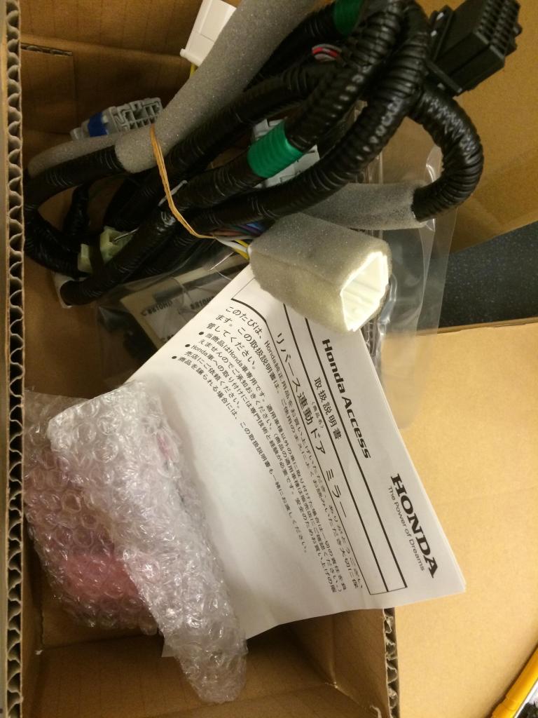
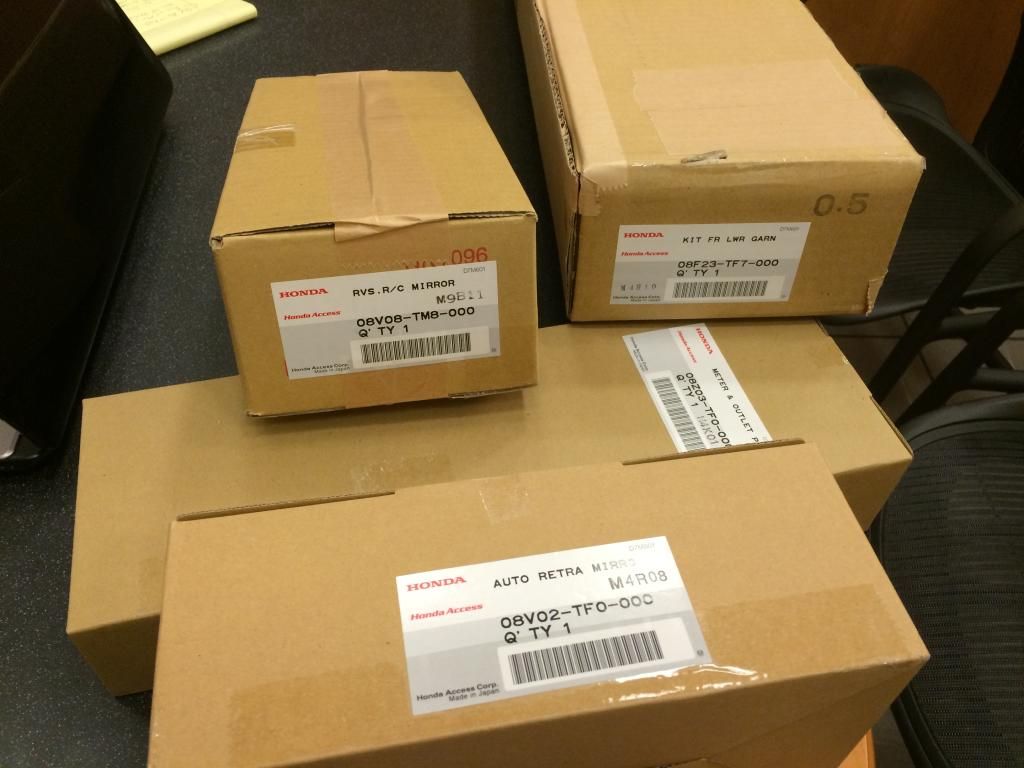
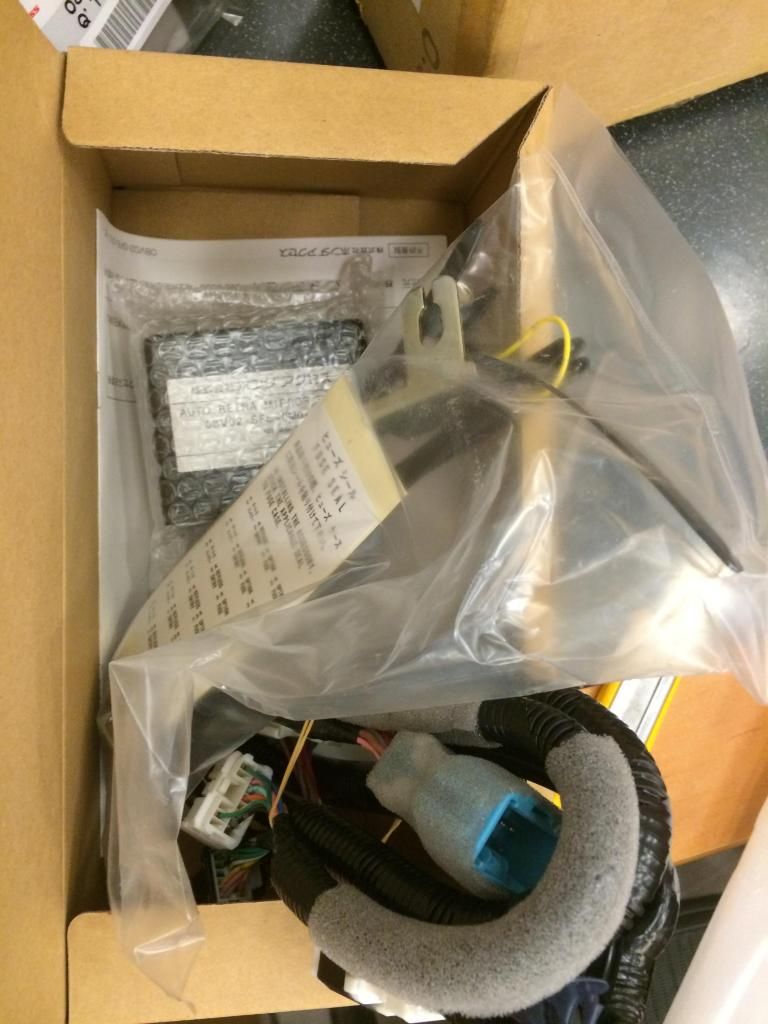
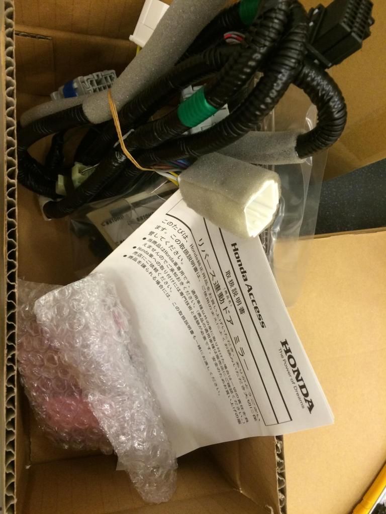
I finally bought the JDM Honda Access Auto TILT
and Auto Folding outside door mirror Wiring and Control Module.
I just need free time to install all this wiring...
which will be challenging since the instruction are all in Japanese


I finally bought the JDM Honda Access Auto TILT
and Auto Folding outside door mirror Wiring and Control Module.
I just need free time to install all this wiring...
which will be challenging since the instruction are all in Japanese

#186
12-25-2014, 02:28 AM
I am trying to learn the wiring...
I think the Auto Folding one will not be hard,
I just had to connect 2 extra wire to the white male socket on the JDM Auto Folding Wire socket
that goes into the Mirror Control Switch for backlighting,
and also connect 2 extra wire that came from the door mirror folding motor
into the original factory USDM Female socket that used to go to the back of the original USDM control switch but now goes to the white male socket from the JDM autofolding wiring.
now, the hard part will be the Autotilt mirror wiring,
especially the Power connector that suppose to connect to the fusebox.
I bought the JDM Honda Insight Auto Tilt mirror wiring, and for now it is not the same
as the JDM Fit Auto folding mirror wiring power connector,
so it can NOT be daisy chained....
hmmmmmmmmmmmm
wait,
speak too soon,
I read the pdf from Fit, Insight and CR-Z,
looks lke the auto folding and auto tilt connect to different socket on the fuse box, so they were not daisy chained after all.
will know tomorrow when I open the fusebox... gotta sleep now... so sleepy
Last edited by BMW ALPINA; 12-25-2014 at 02:46 AM.
#187
12-25-2014, 01:26 PM
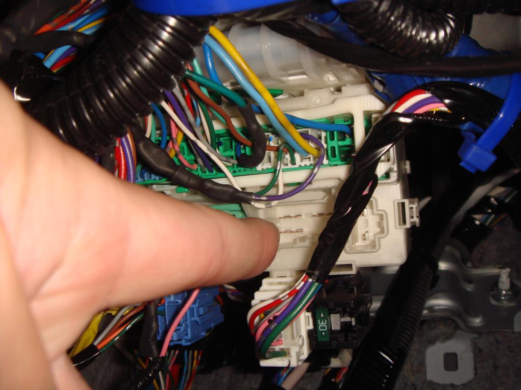
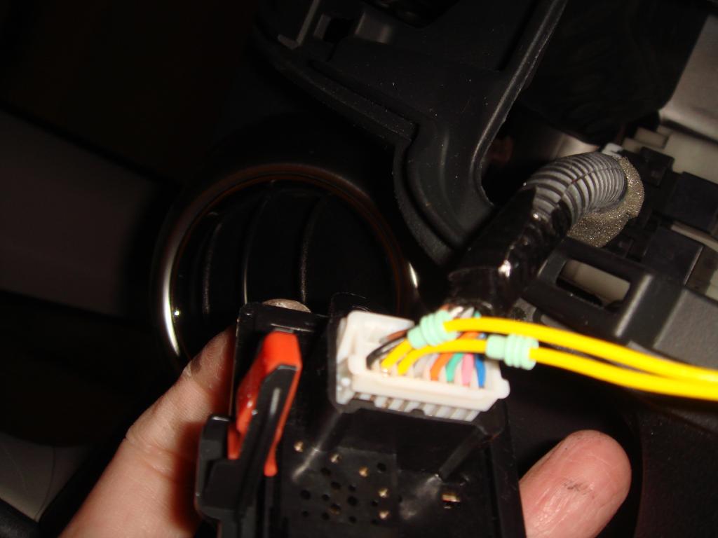
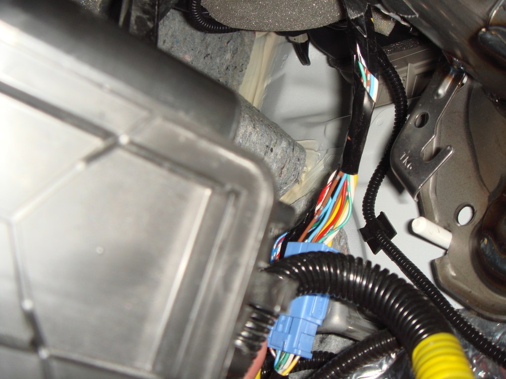
I just found the first problem I had to overcome.
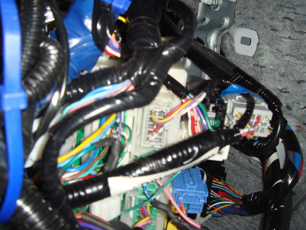
Ok, the good news is the JDM Insight Auto Tilt Wiring socket
that goes into our USDM Fit Fusebox FIT Perfectly,
Here is the picture where the JDM Insight wire will plug into
the fuse box, and I had tested earlier and it fit:
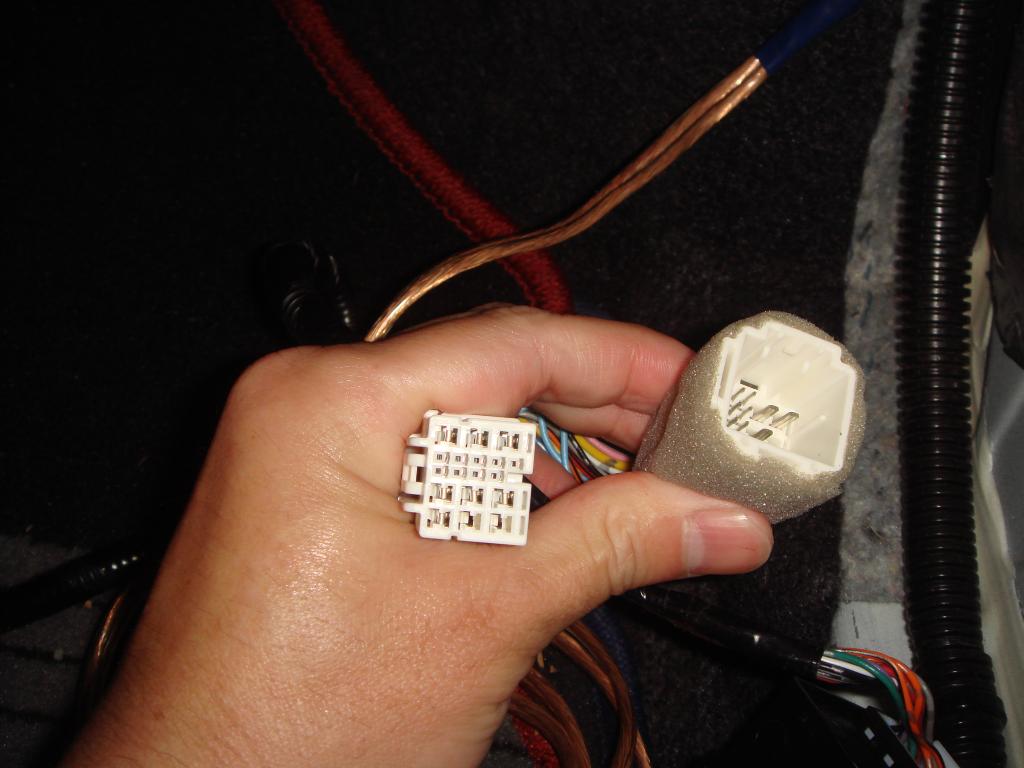
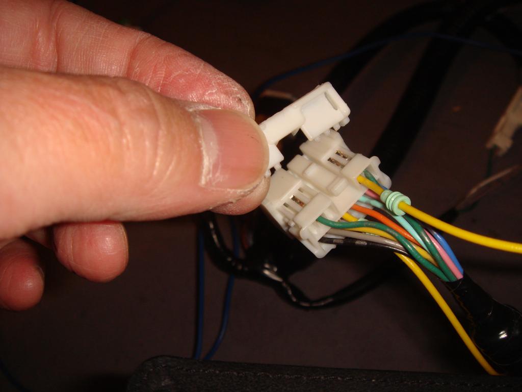
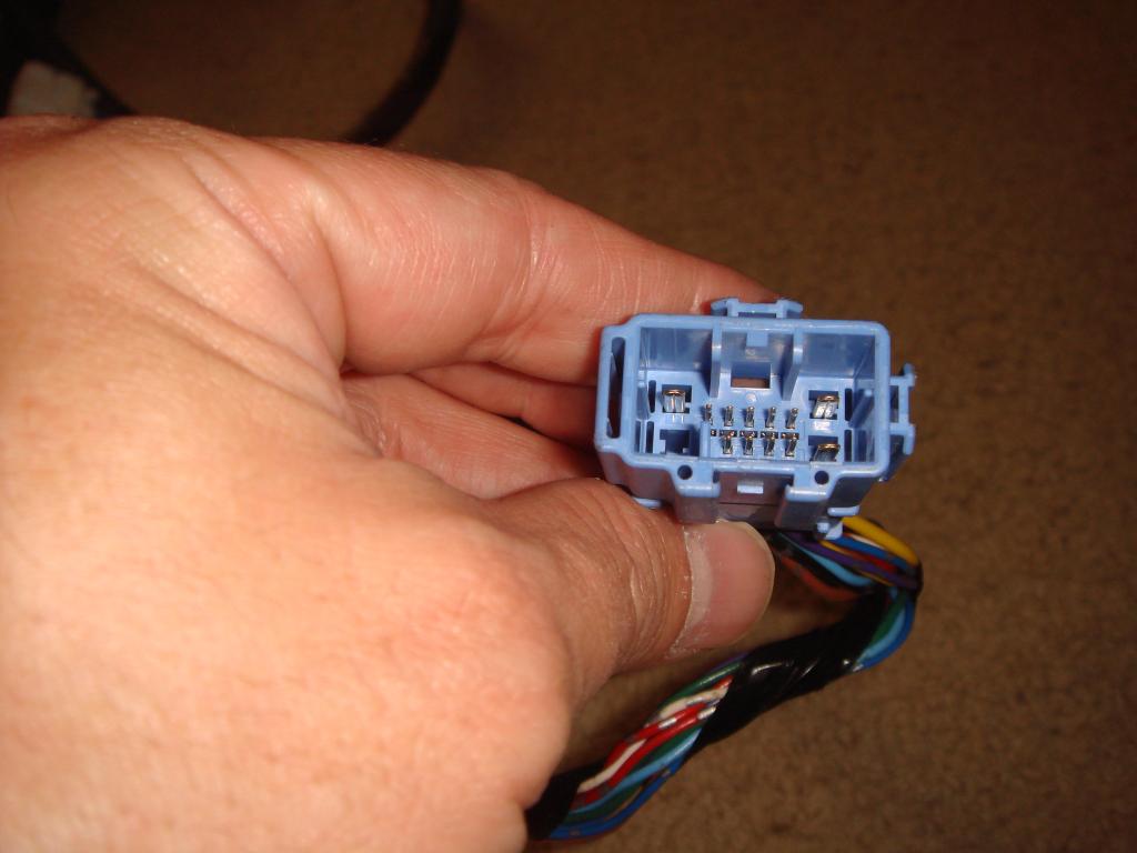
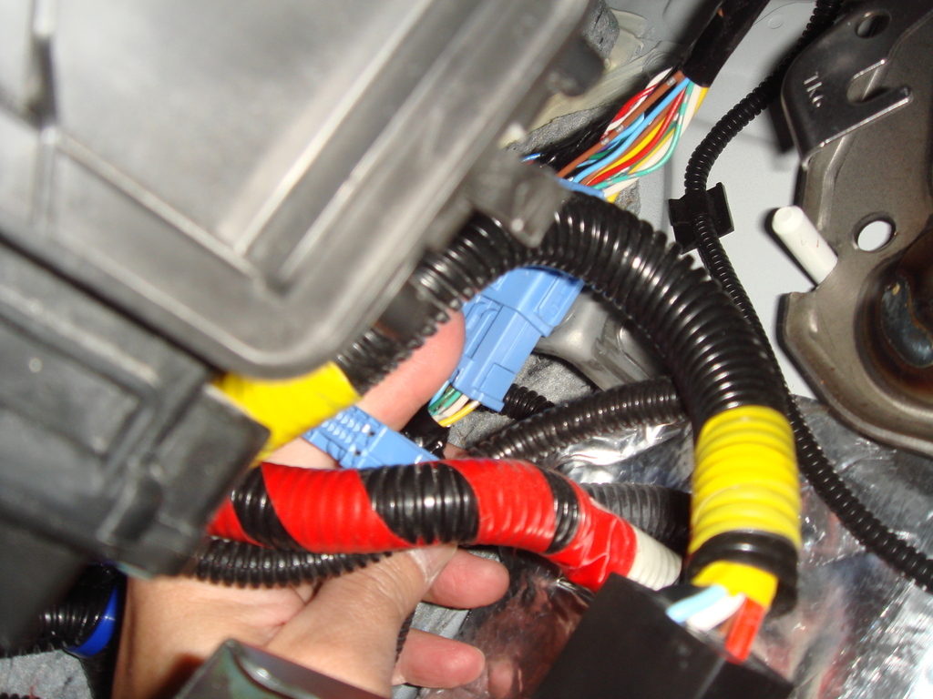
the not so good news is the 2 male and female socket
from the JDM Insight Auto Tilt Wiring are totally
different then the USDM Door Wire male and female socket.
But I am sure I can just by pass some cable,
because the auto tilt function only control the up and down
movement of the servo motor in the door mirror,
so must be only 4 wire that is important,
the other wire is just bypass wire for door lock, door speaker
and left right mirror adjustment...
just need to find which wire is important,
I could of course buy a factory OEM socket...
hmmm
well, lets see,
I am going to do more research, but in the mean time
will install the autofolding function first.
oh by the way,
below is the picture
the JDM insight socket are white,
the USDM door socket are blue:
Ok, the good news is the JDM Insight Auto Tilt Wiring socket
that goes into our USDM Fit Fusebox FIT Perfectly,
Here is the picture where the JDM Insight wire will plug into
the fuse box, and I had tested earlier and it fit:
the not so good news is the 2 male and female socket
from the JDM Insight Auto Tilt Wiring are totally
different then the USDM Door Wire male and female socket.
But I am sure I can just by pass some cable,
because the auto tilt function only control the up and down
movement of the servo motor in the door mirror,
so must be only 4 wire that is important,
the other wire is just bypass wire for door lock, door speaker
and left right mirror adjustment...
just need to find which wire is important,
I could of course buy a factory OEM socket...
hmmm
well, lets see,
I am going to do more research, but in the mean time
will install the autofolding function first.
oh by the way,
below is the picture
the JDM insight socket are white,
the USDM door socket are blue:
#188
12-25-2014, 11:08 PM
I just finished installing the Auto Folding Module,
but I had not install the Auto Tilt Module because I had to do more research
in either getting a USDM door wiring socket and also understand which cable function as what.
Anyway here are the DIY:
Use plastic trim removal tools,
insert in the little slot as picture below and go around to open the
Instrument Panel Cover:
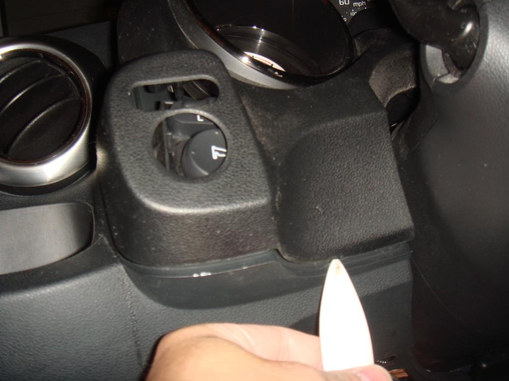
Remove the Mirror Switch (2 screw):
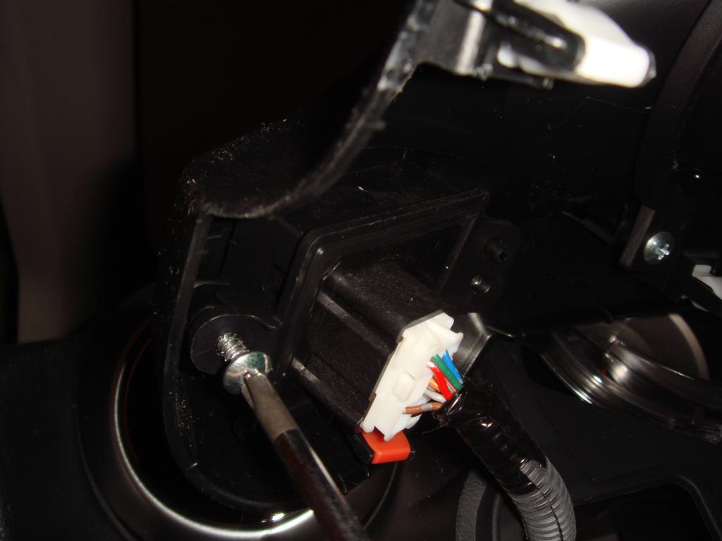
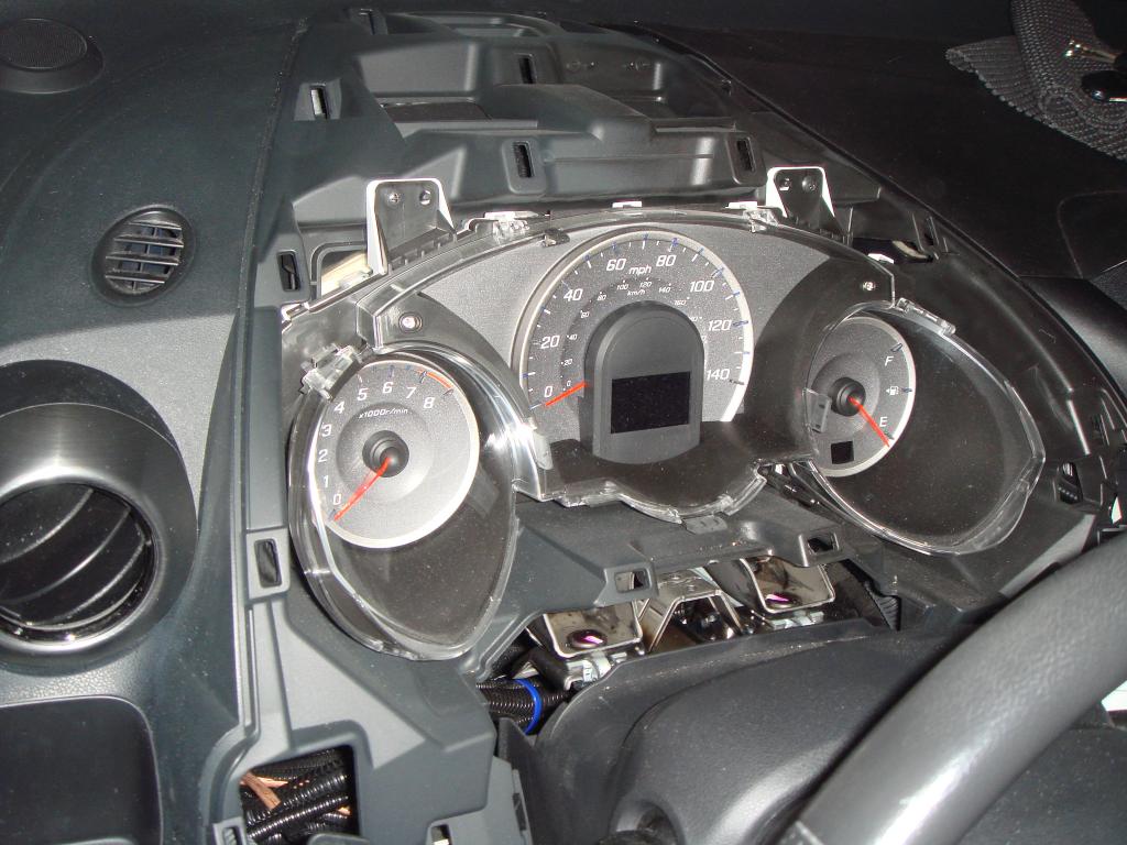
After Instrument Panel Removed:
Insert 2 Pig Tail Wire to the Socket (both the Wiring Module and the Car Wiring):
oh you need to remove the fastener on the socket before
you can insert the pig tail:
Pig Tail Insert:
Test the function make sure the wire is connected well:
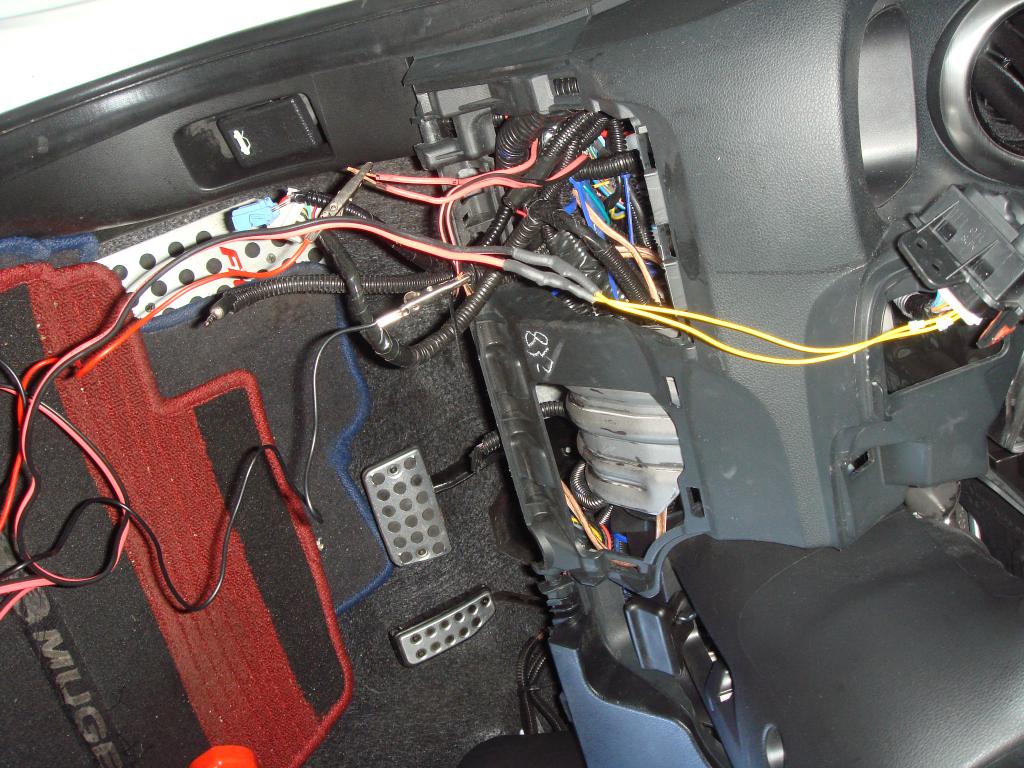
Installing the Control Module:
Start connecting the wiring (run the wiring):
Insert the Fuse Holder and the Jumper on the slot
beside the fuse box. we need that jumper because we don't have the
Keyless System on USDM (I am talking about Rear Keyless system,
where you don't even have to insert key and can start the car/open the door).
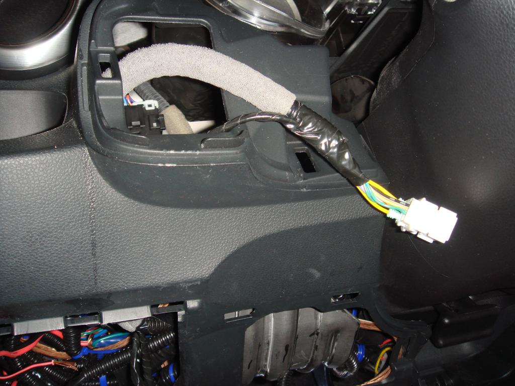
Plug the Power Supply into the fuse box and insert the socket
that was plug before in the daisy chain socket:
Run the cable up to the Remote Switch :
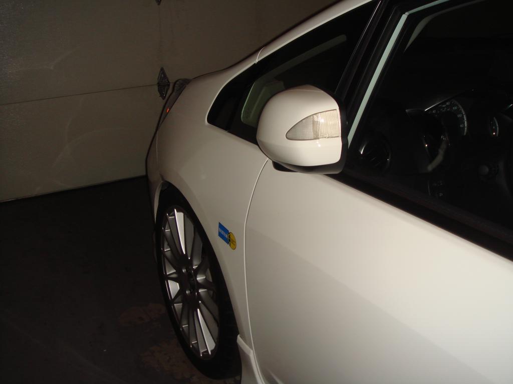
My Mirror finally have the AUTO FOLDING Function
more than 1 year after I install that mirror hahaha:
but I had not install the Auto Tilt Module because I had to do more research
in either getting a USDM door wiring socket and also understand which cable function as what.
Anyway here are the DIY:
Use plastic trim removal tools,
insert in the little slot as picture below and go around to open the
Instrument Panel Cover:
Remove the Mirror Switch (2 screw):
After Instrument Panel Removed:
Insert 2 Pig Tail Wire to the Socket (both the Wiring Module and the Car Wiring):
oh you need to remove the fastener on the socket before
you can insert the pig tail:
Pig Tail Insert:
Test the function make sure the wire is connected well:
Installing the Control Module:
Start connecting the wiring (run the wiring):
Insert the Fuse Holder and the Jumper on the slot
beside the fuse box. we need that jumper because we don't have the
Keyless System on USDM (I am talking about Rear Keyless system,
where you don't even have to insert key and can start the car/open the door).
Plug the Power Supply into the fuse box and insert the socket
that was plug before in the daisy chain socket:
Run the cable up to the Remote Switch :
My Mirror finally have the AUTO FOLDING Function
more than 1 year after I install that mirror hahaha:
#189
12-26-2014, 03:33 AM
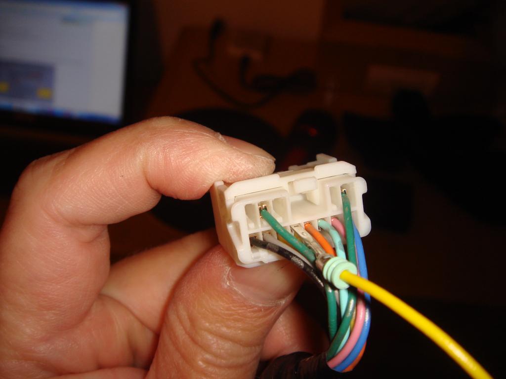
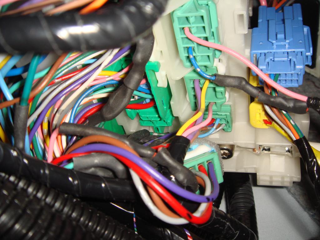
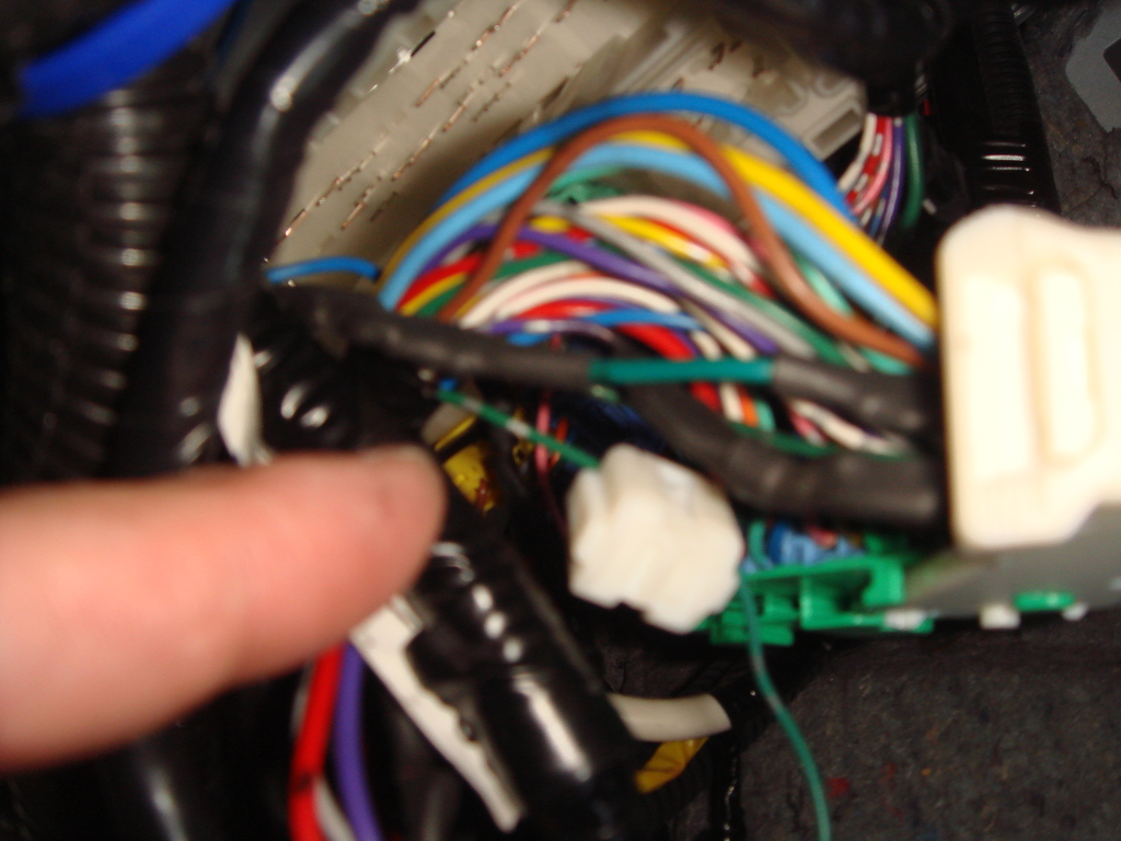
I test the wiring on the male and female socket of the Insight Auto Tilt Module.
Found out most of the wire (except 3 wire) are by passed wire meaning they are always connected and not processed by the module.
The 3 wire that were processed by the module were Red, Orange and Grey, and by looking at the PIN Position that is similar between USDM Fit and JDM Insight socket (only for the low ampere connection/thin wire),
I predict that this is how I need to connect the wire:
For RIGHT Mirror:
Downward Movement:
Insight Wire - (USDM Fit Wire)
Red - (Green) : (Polarity Negative)
Orange - (Light Green) : (Polarity Positive)
Upward Movement:
Insight Wire - (USDM Fit Wire)
Red - (Green) : (Polarity Positive)
Orange - (Light Green) : (Polarity Negative)
Right Movement:
Insight Wire - (USDM Fit Wire)
Orange - (Light Green) : (Polarity Negative)
Grey - (Blue) : (Polarity Positive)
Left Movement:
Insight Wire - (USDM Fit Wire)
Orange - (Light Green) : (Polarity Positive)
Grey - (Blue) : (Polarity Negative)
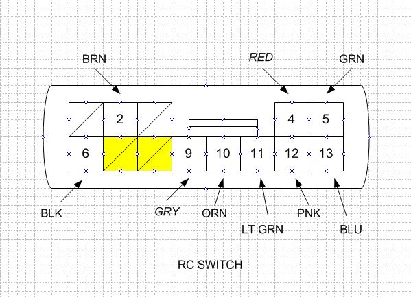
Below is the Diagram where the cable are connected to the RC Switch Pin.
(Pin 5, 11, 13)
so If I want to, I can connect at the RC Switch PIN,
but I think I want to connect at the Socket near the Right Door.
Still, I am going to run some test to make sure the above color connection are correct.
I am going to do it by activating the tilt function by giving 12 volts to the Trigger cable, and see which cable between the Red/Orange/Grey have current flowing then match it to the know Polarity position of the Green,
Light Green and Blue cable.
Most likely I will do this next week when I have my day off again...
oh well...
Found out most of the wire (except 3 wire) are by passed wire meaning they are always connected and not processed by the module.
The 3 wire that were processed by the module were Red, Orange and Grey, and by looking at the PIN Position that is similar between USDM Fit and JDM Insight socket (only for the low ampere connection/thin wire),
I predict that this is how I need to connect the wire:
For RIGHT Mirror:
Downward Movement:
Insight Wire - (USDM Fit Wire)
Red - (Green) : (Polarity Negative)
Orange - (Light Green) : (Polarity Positive)
Upward Movement:
Insight Wire - (USDM Fit Wire)
Red - (Green) : (Polarity Positive)
Orange - (Light Green) : (Polarity Negative)
Right Movement:
Insight Wire - (USDM Fit Wire)
Orange - (Light Green) : (Polarity Negative)
Grey - (Blue) : (Polarity Positive)
Left Movement:
Insight Wire - (USDM Fit Wire)
Orange - (Light Green) : (Polarity Positive)
Grey - (Blue) : (Polarity Negative)
Below is the Diagram where the cable are connected to the RC Switch Pin.
(Pin 5, 11, 13)
so If I want to, I can connect at the RC Switch PIN,
but I think I want to connect at the Socket near the Right Door.
Still, I am going to run some test to make sure the above color connection are correct.
I am going to do it by activating the tilt function by giving 12 volts to the Trigger cable, and see which cable between the Red/Orange/Grey have current flowing then match it to the know Polarity position of the Green,
Light Green and Blue cable.
Most likely I will do this next week when I have my day off again...
oh well...
Last edited by BMW ALPINA; 12-26-2014 at 03:41 AM.
#190
01-16-2015, 11:14 AM
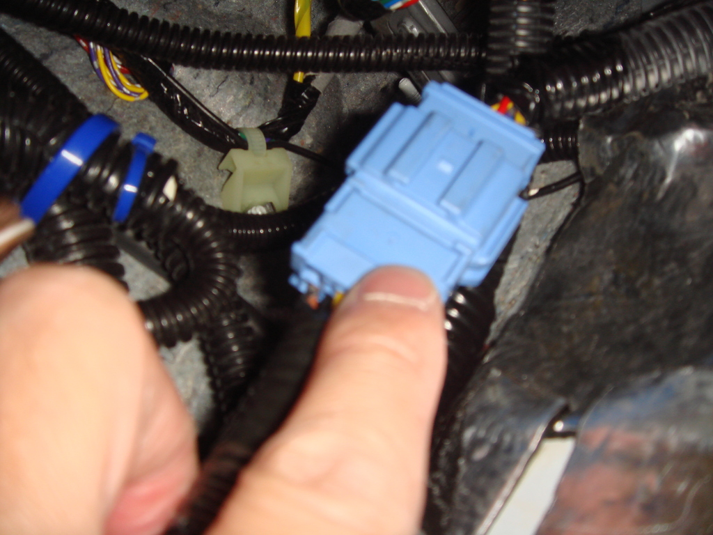
Find the solution for Socket Problem,
I had bought the Entire USDM Fit Dashboard Wiring and the Right Passenger Door Wiring.
I will cut the Blue Male and Female Connector from the USDM Wiring
and soldered them to replace the JDM Honda Insight Connector.
Here are the USDM Fit Dashboard Wiring (with the Male Blue Connector):
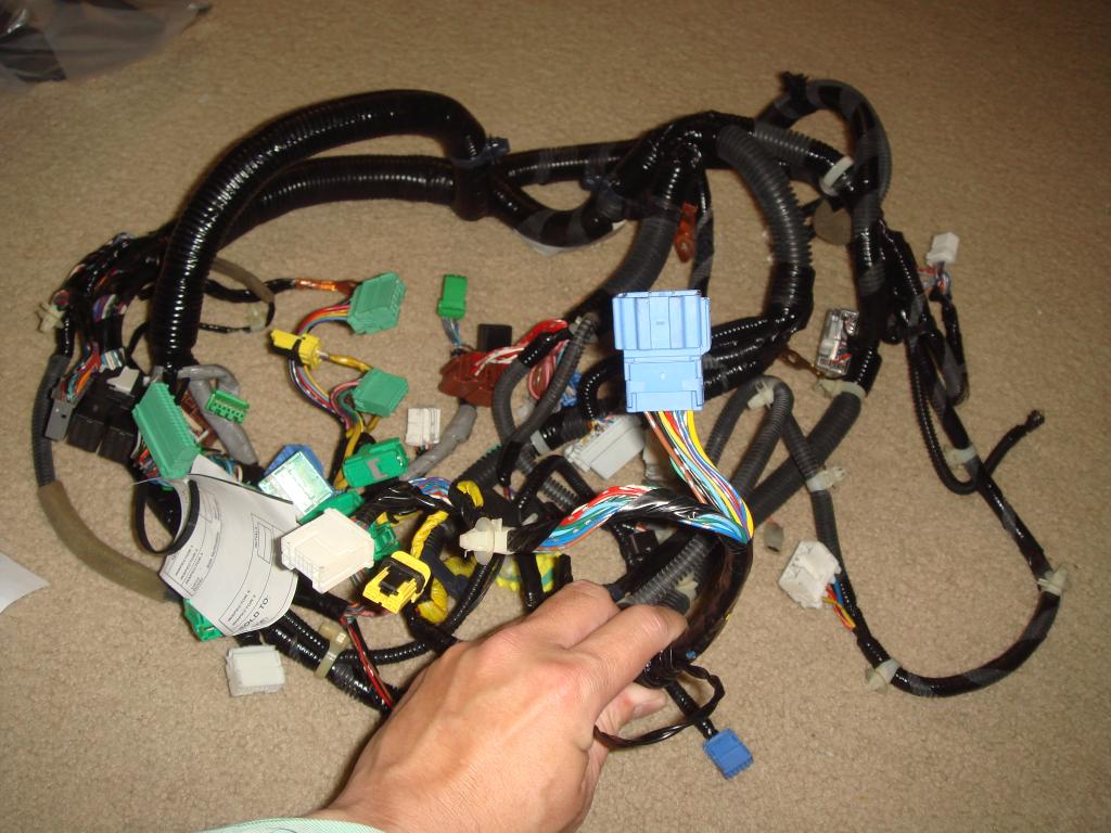
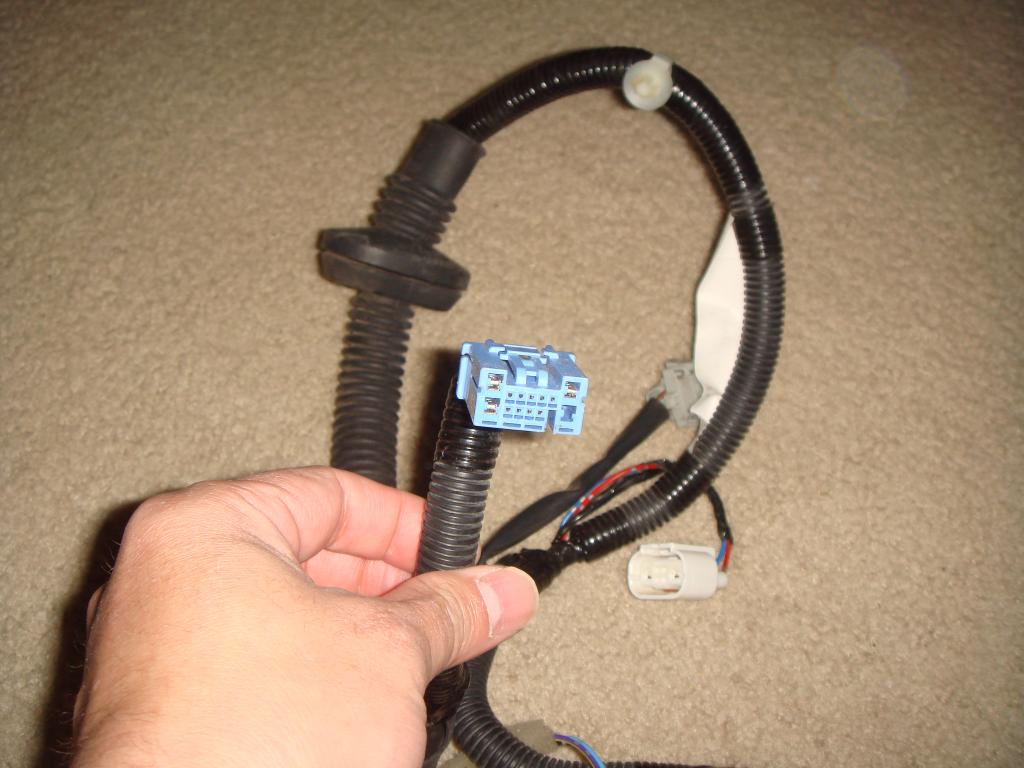
and here are the USDM Fit Right/Passenger Door Wiring with the Female Blue Connector:
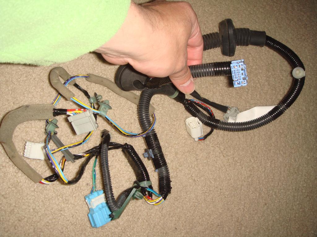
I had bought the Entire USDM Fit Dashboard Wiring and the Right Passenger Door Wiring.
I will cut the Blue Male and Female Connector from the USDM Wiring
and soldered them to replace the JDM Honda Insight Connector.
Here are the USDM Fit Dashboard Wiring (with the Male Blue Connector):
and here are the USDM Fit Right/Passenger Door Wiring with the Female Blue Connector:
#191
03-24-2015, 09:18 PM
After almost TWO (2) years, I finally COMPLETE the installation TODAY!
Yes, I finally installed the last piece of this DIY which is the
Auto REVERSE Tilt Down Function using the Honda Access "Insight" Tilt Reverse Down Module Wiring
with some modification !
First as we know the socket from the Honda Access are NOT compatible
with the socket that goes from the car wiring to the door wiring.
So I cut one socket from the Access wiring,
and then soldered it to one socket that I cut from a complete Honda Fit
dashboard wiring that I bought for this purpose,
and cut another socket from the Honda fit door wiring and soldered it
directly to the Honda Access wiring.
now, I can connect them easily.
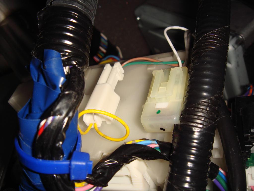
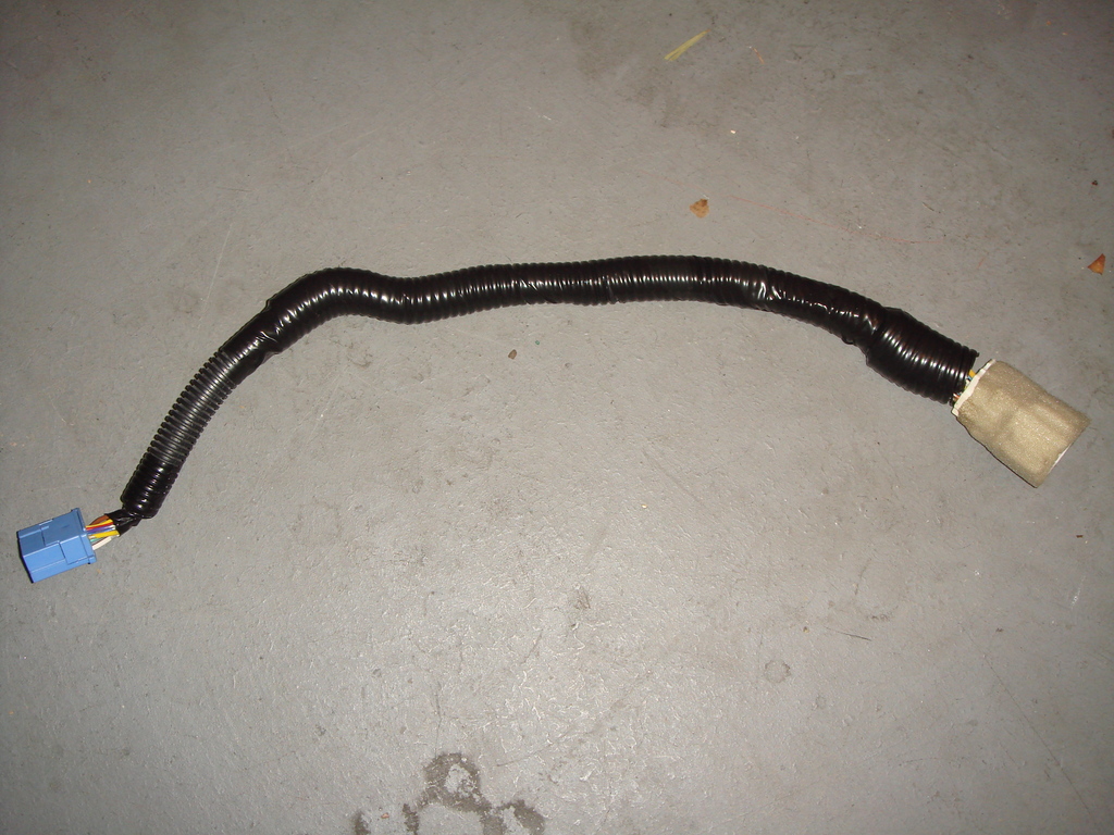
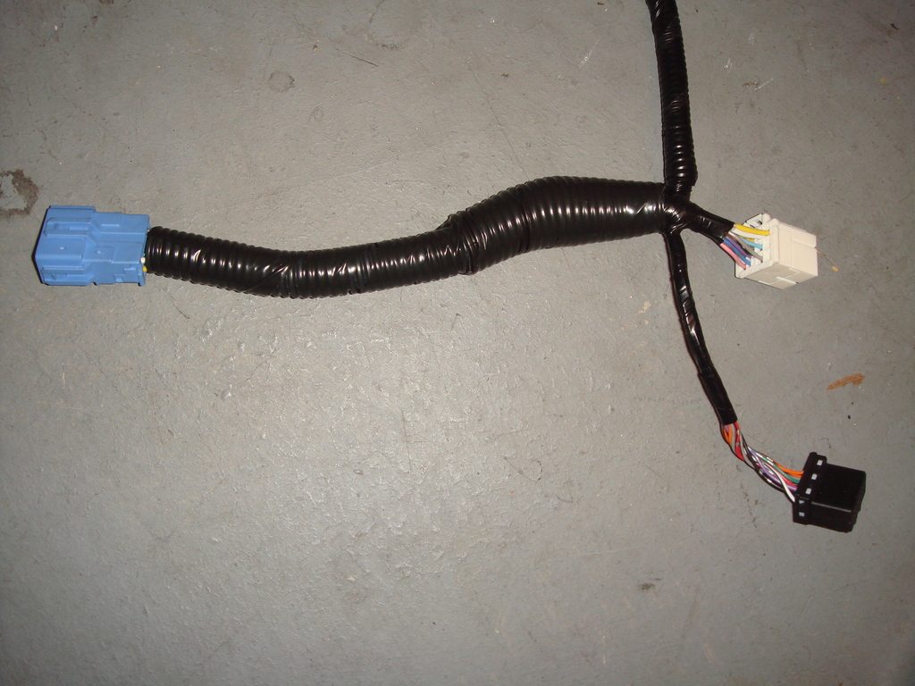
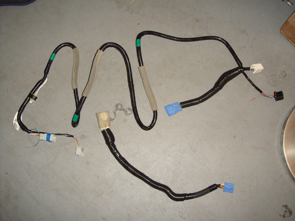
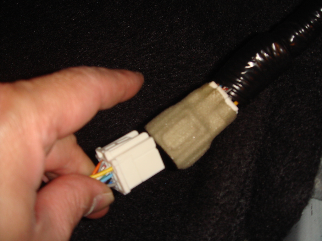
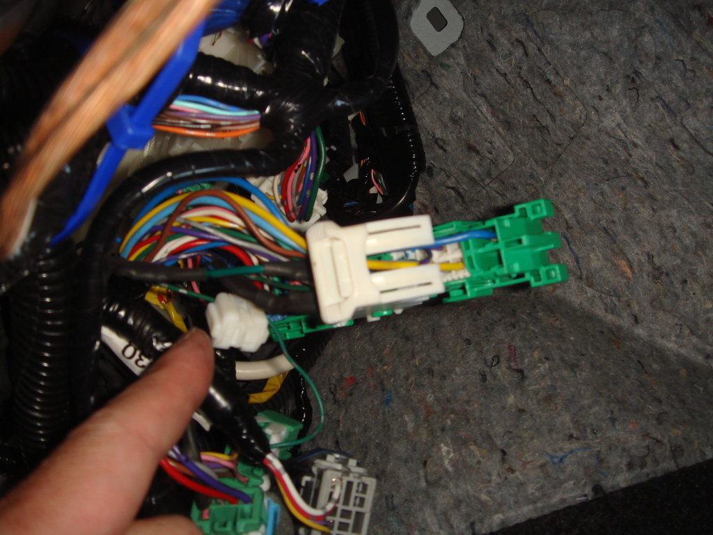
Here are the pictures of the wiring, soldering until I finished with
full protective covering.
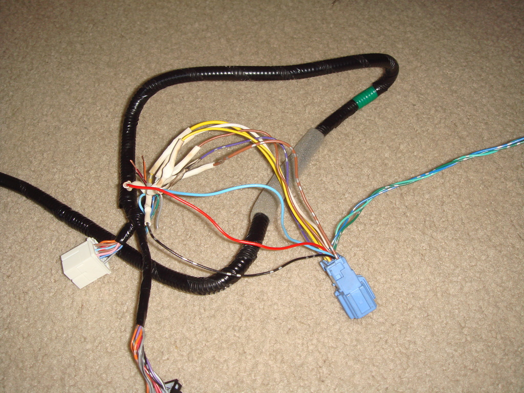
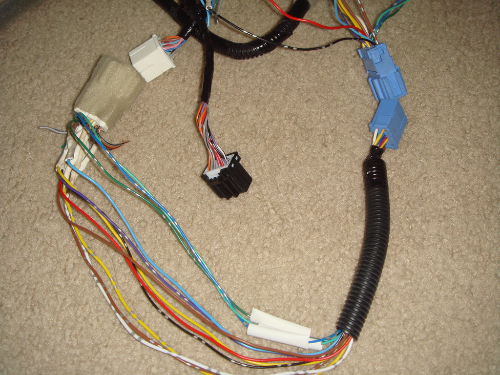
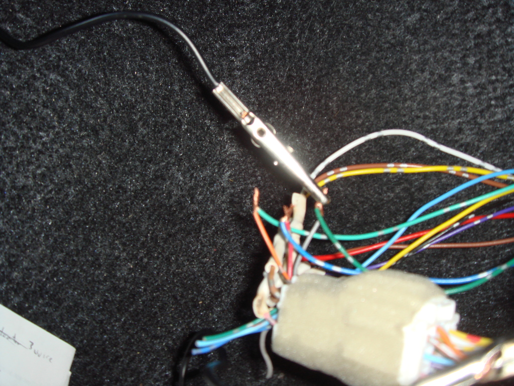
Note the Blue connector came from the Honda Fit Dashboard and Door Wiring, while the White Connector came from the Honda Access Insight wiring.
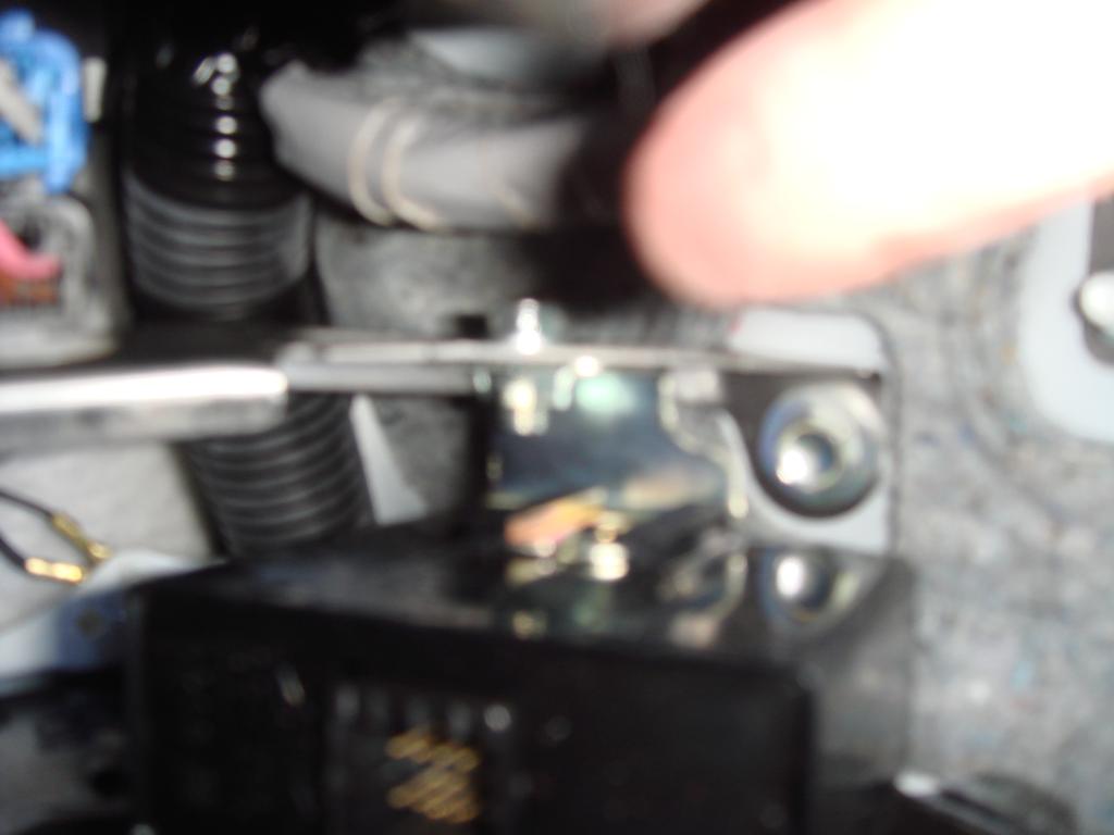
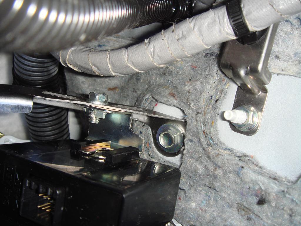
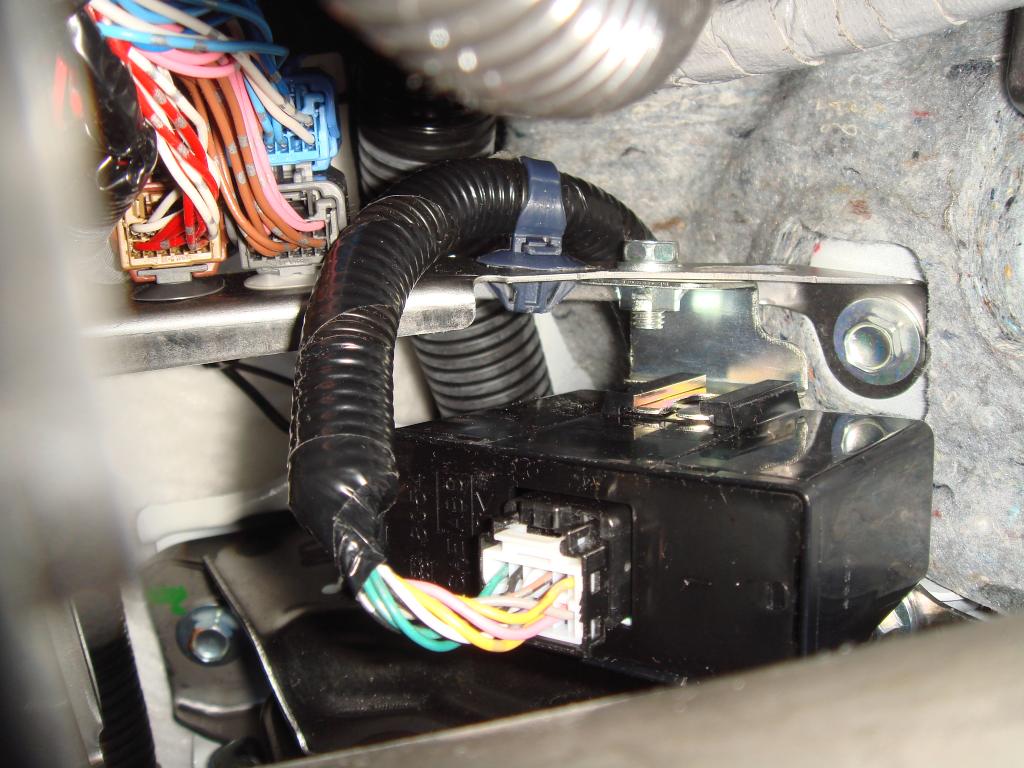
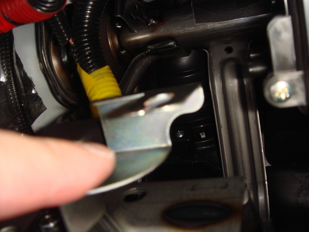
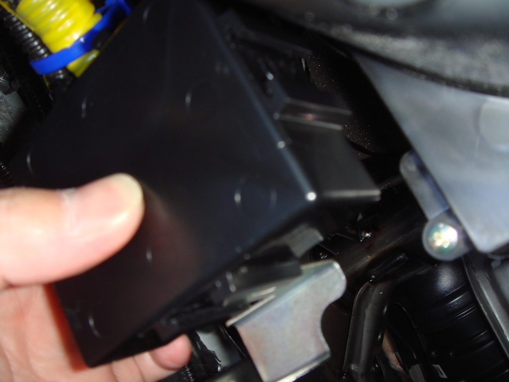
Installing the BRACKET for the CONTROL MODULE that came with the
Honda Access Insight Reverse Tilt Wiring,
I also adjust the setting on this module so it will TILT down at maximum angle ! (there is 4 dip switch).
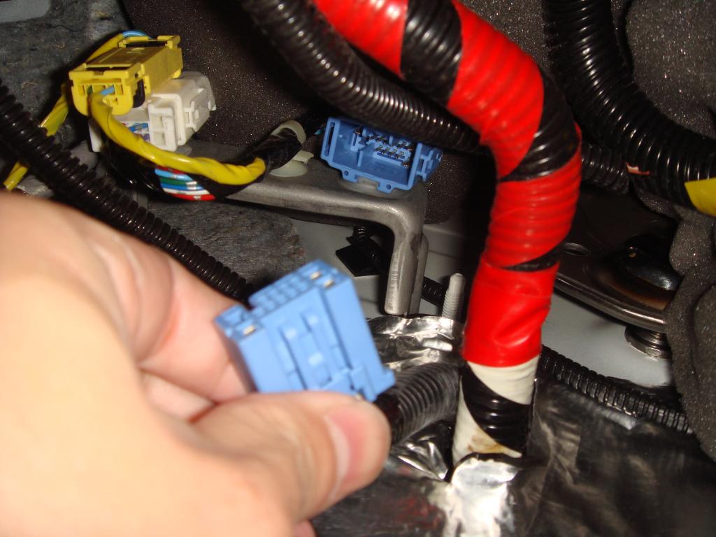
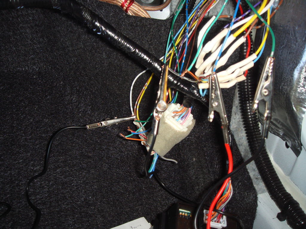
Connecting the wiring:
Using the Tap Module that came with the kit,
I tap the GREEN Wire on the Fuse Box to the Green Wire that goes into the Honda Access wiring, this Green wire provide INPUT/Trigger from Reverse Light to activate the Tilt down:
Yes, I finally installed the last piece of this DIY which is the
Auto REVERSE Tilt Down Function using the Honda Access "Insight" Tilt Reverse Down Module Wiring
with some modification !
First as we know the socket from the Honda Access are NOT compatible
with the socket that goes from the car wiring to the door wiring.
So I cut one socket from the Access wiring,
and then soldered it to one socket that I cut from a complete Honda Fit
dashboard wiring that I bought for this purpose,
and cut another socket from the Honda fit door wiring and soldered it
directly to the Honda Access wiring.
now, I can connect them easily.
Here are the pictures of the wiring, soldering until I finished with
full protective covering.
Note the Blue connector came from the Honda Fit Dashboard and Door Wiring, while the White Connector came from the Honda Access Insight wiring.
Installing the BRACKET for the CONTROL MODULE that came with the
Honda Access Insight Reverse Tilt Wiring,
I also adjust the setting on this module so it will TILT down at maximum angle ! (there is 4 dip switch).
Connecting the wiring:
Using the Tap Module that came with the kit,
I tap the GREEN Wire on the Fuse Box to the Green Wire that goes into the Honda Access wiring, this Green wire provide INPUT/Trigger from Reverse Light to activate the Tilt down:
Last edited by BMW ALPINA; 03-24-2015 at 09:31 PM.
#193
03-25-2015, 02:42 AM
but let's see...
the 2 folding mirror were used so they are about $400 including shipping...
plus around $100 for the new outside cover...
the switch (CR-V) maybe $50,
the cabling and other cost maybe $100, (including relays for the blink function when I arm the alarm, the cable jacket, the socket, the pig tail,the soldering bla bla bla),
the Honda Access Auto Folding Wiring and Honda Access Auto Reverse tilt perhaps another $250 include shipping,
the Honda Fit USDM dashboard wiring and door mirror (used) perhaps another $100,
so Total cost $1,000 already...
lucky I install on my own, so not installation cost...
otherwise hahaha...
ups, correction, the 2 folding mirror were only $300 pair not $400...
so the Total cost is $900 now hahaha
Last edited by BMW ALPINA; 03-25-2015 at 02:46 AM.

#195
06-28-2015, 11:21 AM
if that so, the door socket is on the passenger side.
but the JDM door socket that came with the wiring kit is different
then the USDM door socket.
so you either had to splice the wiring or buy a full dashboard wiring from junkyard and use the socket to replace the JDM socket.
#196
10-15-2015, 10:52 PM

I must say.... I love you and your write ups very informative and all the info is there. This was one of the first things I looked into.
#197
12-17-2017, 12:50 AM

I just wanna thank you for gathering info from other places and putting it into one! I just installed my 7 pin CF Mugen covered powerfolding mirrors using this writeup and installation was a breeze. (Except putting wires through the DS grommet lol never again)
#198
01-12-2019, 08:09 AM

Honda fit shutlle GG-7
After more than 1 year,
I finally bought the JDM Honda Access Auto TILT
and Auto Folding outside door mirror Wiring and Control Module.
I just need free time to install all this wiring...
which will be challenging since the instruction are all in Japanese
Attachment 12888
Attachment 12889
Attachment 12890
I finally bought the JDM Honda Access Auto TILT
and Auto Folding outside door mirror Wiring and Control Module.
I just need free time to install all this wiring...
which will be challenging since the instruction are all in Japanese
Attachment 12888
Attachment 12889
Attachment 12890
Здравствуйте .помогите советом .у меня в автомобиле установлен блок 08v02-sfe-0m0-01 автоматическое складывание зеркал при постановке на охрану.как мне отключить эту функцию.может у вас есть распиновка этого блока
#199
11-17-2023, 03:08 PM

I know this is way old.....but i can get these mirrors for 200cad shipped...folding and indicator only..PERFECT.....they are 7 pin.will this be plug and play with 2013 sport?

Thread
Thread Starter
Forum
Replies
Last Post