DIY: 11 Pin Door Mirror (Folding, Heated, Smart Key)
#61
 05-21-2013, 02:43 AM


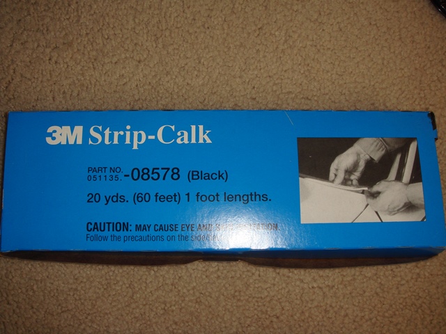
Package from Amazon.com arrive today,
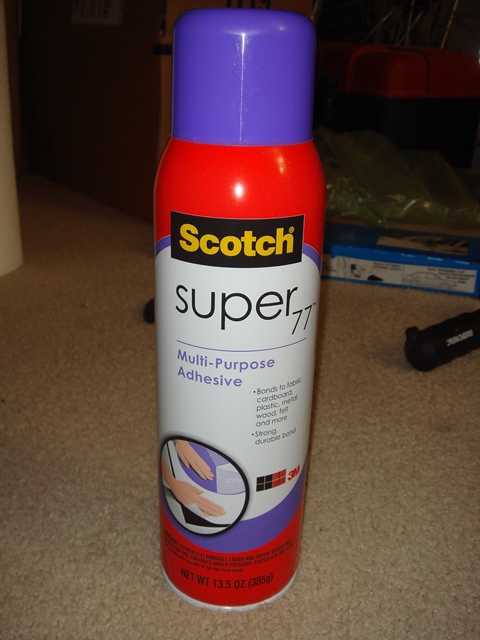
it contain the 3M CALK and also the 3M Super 77 glue for foam that I had been waiting for.
When I dissemble the mirror (glass) from the housing,
I notice Honda factory add some Black Sticky Calk to help attached the mirror to the actuator and also dampened some vibration so the mirror (glass) would not vibrate and make it hard to see.
I see that this Black Sticky Calk is no longer enough after I took the mirror out from the housing.
so I do some research and finally found that 3M made that same Black Sticky Calk and I ordered from Amazon.
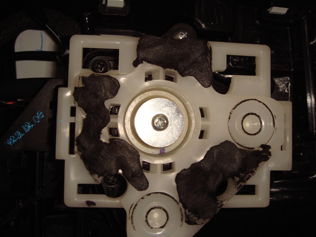
Then I apply the 3M CALK strip to the white plastic actuator,
and then I attached the mirror/glass to the white plastic actuator.
Here are the pictures:
Pictures of the Strip of Calk:
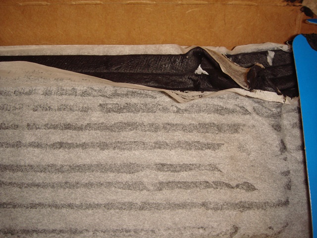
3M Calk applied :
Then I also see that between the mounting feet of the mirror assembly and the car door, they have this rubber with extra FOAM attached to it...
but after a while that FOAM had became FLAT,
so I cut some FOAM and attached it to the Mounting Feet,
some part of the FOAM were attached with the 3M Super 77 Glue.
Here are the pictures:
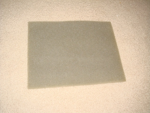
The sheet of foam from some old packaging:
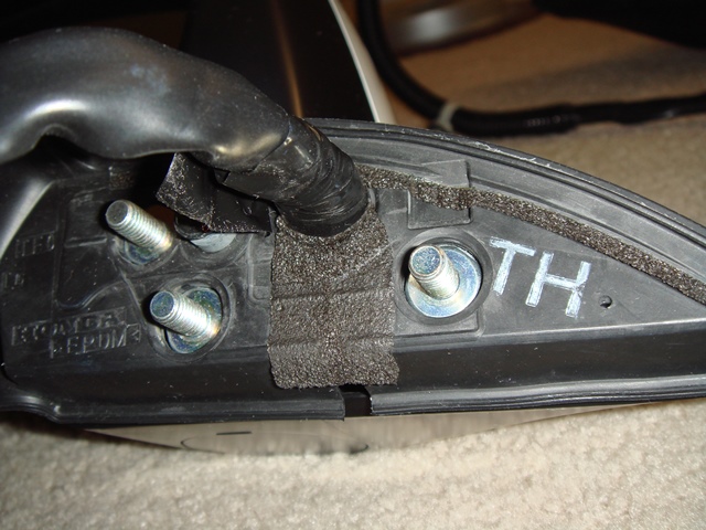
Mounting Feet with the OLD FLAT Foam:
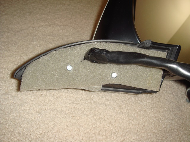
New Foam applied on both Mounting Feet:
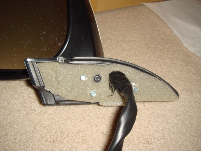
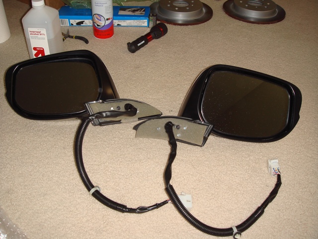
Finally both mirror ready to be installed on my car's door
I hope,
I can start installing this 2 door mirror on my car tomorrow,
but for the time being I will only have blinking and heated function.
I do not want to install the CR-V mirror switch yet cause it involved opening the dashboard panel until I have the JDM auto folding and auto tilt function.
so no folding function for the time being.
it contain the 3M CALK and also the 3M Super 77 glue for foam that I had been waiting for.
When I dissemble the mirror (glass) from the housing,
I notice Honda factory add some Black Sticky Calk to help attached the mirror to the actuator and also dampened some vibration so the mirror (glass) would not vibrate and make it hard to see.
I see that this Black Sticky Calk is no longer enough after I took the mirror out from the housing.
so I do some research and finally found that 3M made that same Black Sticky Calk and I ordered from Amazon.
Then I apply the 3M CALK strip to the white plastic actuator,
and then I attached the mirror/glass to the white plastic actuator.
Here are the pictures:
Pictures of the Strip of Calk:
3M Calk applied :
Then I also see that between the mounting feet of the mirror assembly and the car door, they have this rubber with extra FOAM attached to it...
but after a while that FOAM had became FLAT,
so I cut some FOAM and attached it to the Mounting Feet,
some part of the FOAM were attached with the 3M Super 77 Glue.
Here are the pictures:
The sheet of foam from some old packaging:
Mounting Feet with the OLD FLAT Foam:
New Foam applied on both Mounting Feet:
Finally both mirror ready to be installed on my car's door
I hope,
I can start installing this 2 door mirror on my car tomorrow,
but for the time being I will only have blinking and heated function.
I do not want to install the CR-V mirror switch yet cause it involved opening the dashboard panel until I have the JDM auto folding and auto tilt function.
so no folding function for the time being.
#62
05-22-2013, 02:04 AM
Spent whole day installing the Left JDM Mirror,
initially, everything went smooth,
until I found out my MOLEX socket were to big to fit the hole where the cable from the mirror enter the door !!!
Quickly go to Frys to buy other Molex Connector (I used the PC power cable extension), will post pictures later...
then spent more than 2 hours wresting with the rubber boot,...
I am really tired and my hand sore, my nail bleeding until I remember,
I had a silicone grease spray can...
then I spray silicone grease into the rubber boot and voila,
the stuck cable just came out so easy...
Damn, if I know this, I would had lot of time and avoid bleeding nail...
FYI, I am jamming 6 piece of 18 awg wire (heater, folding, blinker) PLUS
2 piece of 14awg wire that I plan to use for future Mid Bass Upgrade,...
so yeah it is pretty tight inside that rubber boot...
what is worse is, it seemed that when I am forcing those wire, I manage to break one wire for Door LOCKING...
Now my Door Locking switch only able to unlock but can not LOCK the door !!! (sometimes work, sometimes don't work)...
but this also could be from me trying to remove the KARR alarm module and wiring that pre installed by the dealer (but not activated)...
so this will be complicated !!!
If anybody here knew the Pin Out Diagram (or wire color) for Driver Side Door Lock/Power Window socket/switch assembly, please kindly let me know,...
so I don't have to do many testing using multimeter...
I had look in the service manual and wiring diagram, but I had not found the Pin Diagram...
All I need is to find the wire that function to lock the door when you press the switch, so I can test whether that wire broken or not...
Last edited by BMW ALPINA; 05-22-2013 at 02:08 AM.
#63
05-22-2013, 02:18 AM
lol i could have told u that trying to get the wires thru that rubber boot is a PITA! the best way i found out is to get a wire hanger and make a hook in the end and loop your wires thru it. wrap it tight with electrical tape. then take the end that is just wire and push it through the bottom of the boot going up. when the wire sticks out, take a pair of pliers and grab the wire and pull it through until u see your electrical wiring coming out the other end. i also found that if u cut the wire hanger so its not so long makes it easier for you to route it through the grommet.
when ur done, make sure u route the wires behind the little panel inside the doors, or else when ur window comes down, your wires will get caught under it.
when ur done, make sure u route the wires behind the little panel inside the doors, or else when ur window comes down, your wires will get caught under it.
#64
05-22-2013, 04:26 AM
lol i could have told u that trying to get the wires thru that rubber boot is a PITA! the best way i found out is to get a wire hanger and make a hook in the end and loop your wires thru it. wrap it tight with electrical tape. then take the end that is just wire and push it through the bottom of the boot going up. when the wire sticks out, take a pair of pliers and grab the wire and pull it through until u see your electrical wiring coming out the other end. i also found that if u cut the wire hanger so its not so long makes it easier for you to route it through the grommet.
when ur done, make sure u route the wires behind the little panel inside the doors, or else when ur window comes down, your wires will get caught under it.
when ur done, make sure u route the wires behind the little panel inside the doors, or else when ur window comes down, your wires will get caught under it.
so I already prepared myself with all the tools and method (except I forget about my silicone grease...)
but
then most people here only pushing around 2 to 6 wire only...
2 if just doing LED Blinker
4 if doing LED Blinker and Auto Folding
6 if doing LED Blinker, Auto Folding and Heater,
but I am doing more, 6 wire of the above (all 18awg)
plus 2 thick 14AWG wire for future Mid Bass Speaker,
so my difficulties is... well let just say blood and sweat is needed hahaha (literally since my nail is bleeding...)...
I also used the proven method of using coat hanger wire
(in my case I use thick cooper solid wire which is should be even better then coat hanger
due to flexibility yet still solid enough)...
the problem though I need to push 8 wire !!!
Well, as I had post above, now I know the solution,
SILICONE GREASE,
cause as soon as I spray the inside of the rubber boot with silicone grease,
the wire just pass through so so easily !!!
Damn,... I should use the silicone grease from the start,
well there is always the passenger side door that still need to be done
so for everybody who attempt to pass wire through the rubber boat with coat hanger,
don't forget to spray the inside of the rubber boot with silicone grease, it will make it so much easier.
The silicone grease also will not harm the rubber or the wire jacket,
so it is safe, just make sure you don't use other kind of grease !!!
ok,
now about the wiring for the door lock switch,
I had finally found it...
on the service manual there is a section for testing the Power Window Wiring,
and the door look switch wiring is combined with the Power Window wiring,
but unfortunately on that service manual,
it only explain about the Power Window wiring only... no pin out explanation for door lock switch...
so what I did was,
I deduct the wiring used for power window from the Socket Pin Out diagram,
and all it's left is just the Pin Out of the door lock switch...
VOILA, that is my door lock window switch...
later, I do more search and found a diagram wiring under section MICU,
and this one show the Door Lock Switch wiring and pin out number,
and it MATCH with my previous found from the power window service manual,...
so now I am 100% sure that I had found the correct wiring...
All I need to do know is to find the same door lock wiring near the fuse box
so I can test whether the wire is broken or not...
I think I can find it easy by following the wire tapped by that KARR alarm...
those KARR alarm must tapped the door locking function
if the wire turn out to have broken connection,
I already have solution,
On my wiring for door mirror, I have 2 GROUND wiring,
one ground wire for heater and one ground wire for the LED blinker,
both of them have same AWG size (18 AWG),
that mean I can combine the LED Blinker ground with the heater ground,
so Now I have one extra wiring that ready to be utilized to replace the broken wire on the door lock switch wiring if I need too
No need to run another wire through that rubber boot !
Ok,
the Door Wiring is in Pin Number 17 and 19 of the Power Window Connector terminal (female terminals)...
Number 17 color Light Blue is for Locking the door when it have + current
Number 19 color Grey is for UNLOCKING the door when it have + current...
that mean I need to check the Number 17 (Light Blue Wire) for locking,
cause I can NOT lock my car with the switch now !
anyway, I am busy tomorrow, so I might not be able to solve this until Thursday or Friday...
Now I can go to sleep with peaceful mind knowing that I had already find the solution for my door lock switch problem
again, don't forget silicone grease for passing wire through rubber boot
Last edited by BMW ALPINA; 05-22-2013 at 04:32 AM.


#66
05-22-2013, 07:30 AM
Thanks Loudbang,
by the way,
I couldn't sleep thinking on how I am going to find the wire near the fusebox that correspond to the door locking/unlocking from the switch...
and then I remember that damn Karr Alarm that I never ask and the wiring is a mess (just see it today)...
but it is also a blessing as guidance...
so if I can find the Karr Alarm wiring diagram, I can trace it back to find the Honda factory wiring for lock/unlock
after several searches with Google,
I manage to find several different Karr Alarm model wiring,
will check soon to see which Karr Alarm that I had,
and will post the Karr Alarm wiring diagram here, hopefully,
it can help others who want to know the wiring diagram of their Karr Alarm
time for me to go back to sleep now
#67
05-22-2013, 08:49 AM

BMW_ALPINA,
Do you have this bookmark? Yes it is for GD1 but I think GD1 and GE are quite similar.
Wiring Diagram Index
Do you have this bookmark? Yes it is for GD1 but I think GD1 and GE are quite similar.
Wiring Diagram Index
#68
05-22-2013, 11:57 AM
BMW_ALPINA,
Do you have this bookmark? Yes it is for GD1 but I think GD1 and GE are quite similar.
Wiring Diagram Index
Do you have this bookmark? Yes it is for GD1 but I think GD1 and GE are quite similar.
Wiring Diagram Index
Thanks for your information,
but I already have downloaded the entire GE8 service manual and wiring diagram.
It is in the confusing HTML format (not PDF) and can only be opened by internet explorer only (no firefox/google chrome)
it is just that the interface format to access it's page is so not user friendly,...
I downloaded from the link available on one of fitfreak.net post
this is the link to that thread:
https://www.fitfreak.net/forums/2nd-...ml#post1169076
#69
05-22-2013, 01:16 PM

I've seen electricians use some lube for snaking wires... looks like I'll definitely be getting some...
I think the auto-fold mechanism should last well over 3 yrs even if used several times a day... my concern is over the long-long-long term since I plan on keeping this car as long as possible.... even still if you have to replace the motors once it's still worth it... you can then get the LHD motors for better viewing angle(?)
from fitfans.br
Fit Fans Forum - DIY auto-fold
Alpina, this is what I meant in an earlier post regarding LHD/RHD differences (viewing angles).
I think the auto-fold mechanism should last well over 3 yrs even if used several times a day... my concern is over the long-long-long term since I plan on keeping this car as long as possible.... even still if you have to replace the motors once it's still worth it... you can then get the LHD motors for better viewing angle(?)
from fitfans.br
Fit Fans Forum - DIY auto-fold
Motores RHD para pa�ses com m�o Direita (Inglaterra, Jap�o...)
- Motor do rebatedor do retrovisor lado direito - Part Number : 76204-TF0-E31
- Motor do rebatedor do retrovisor lado esquerdo - Part Number : 76254-TF0-E31
Ou
Motores LHD para pa�ses com m�o Esquerda (Brasil, Alemanha e etc).
Os PartNumbers para o �ngulo de visualiza��o LHD s�o:
- Motor do rebatedor do retrovisor lado Direito 76204-TF0-P01
- Motor do rebatedor do retrovisor lado Esquerdo 76254-TF0-P01
#70
05-22-2013, 01:23 PM
I've seen electricians use some lube for snaking wires... looks like I'll definitely be getting some...
I think the auto-fold mechanism should last well over 3 yrs even if used several times a day... my concern is over the long-long-long term since I plan on keeping this car as long as possible.... even still if you have to replace the motors once it's still worth it... you can then get the LHD motors for better viewing angle(?)
from fitfans.br
Fit Fans Forum - DIY auto-fold
Alpina, this is what I meant in an earlier post regarding LHD/RHD differences (viewing angles).
I think the auto-fold mechanism should last well over 3 yrs even if used several times a day... my concern is over the long-long-long term since I plan on keeping this car as long as possible.... even still if you have to replace the motors once it's still worth it... you can then get the LHD motors for better viewing angle(?)
from fitfans.br
Fit Fans Forum - DIY auto-fold
Alpina, this is what I meant in an earlier post regarding LHD/RHD differences (viewing angles).
so far I had only installed the Driver side window,
and the JDM Driver side door mirror had good viewing angle,
but
maybe there will be limitation on the Passenger (Right) door mirror viewing angle...
I will find out soon
if it is dangerous then I have to take out my stock USDM mirror actuator motor and install in my JDM mirror, but hopefully I don't have to do it,
cause I rather sell my stock USDM door mirror and get more money to buy more modification
#71
05-22-2013, 02:02 PM
That's farther than I got... I only installed the CR-V switch... It looks great at night. 
I still can't decide on if I want the auto-fold harness, but I will probably buy it anyway.... Can't wait to get those blue heated mirrors that you posted earlier... and on second thought I will hook up the signal on the mirror as well. I've seen quite a few newer cars with both signals on the glass, and the mirror cover... if you think about it they serve different blindspots (for the lack of better term) for other drivers next to you.
As for viewing angle.... from page 15 the thread previously linked Fit Fans Forum - Exibir t�pico - Rebatimento Autom�tico dos Retrovisores
It's all Portuguese to me. 
I still can't decide on if I want the auto-fold harness, but I will probably buy it anyway.... Can't wait to get those blue heated mirrors that you posted earlier... and on second thought I will hook up the signal on the mirror as well. I've seen quite a few newer cars with both signals on the glass, and the mirror cover... if you think about it they serve different blindspots (for the lack of better term) for other drivers next to you.
As for viewing angle.... from page 15 the thread previously linked Fit Fans Forum - Exibir t�pico - Rebatimento Autom�tico dos Retrovisores
Ilustrando Melhor:

#72
05-22-2013, 04:59 PM
It is interesting that you guys are getting the information from the Fit forum in Brazil I have talked to a few members there since I am living in Brazil now.
The Honda parts in Brazil are very expensive (if case you are thinking buying parts/accessories here, about x2 or x3 on average, e.g., 1 qt of Mobil 1 Syn ranges from $20 to $30 USD). I brought all my oil/air/cabinet filter from the states.
I have talked to a few members there since I am living in Brazil now.The Honda parts in Brazil are very expensive (if case you are thinking buying parts/accessories here, about x2 or x3 on average, e.g., 1 qt of Mobil 1 Syn ranges from $20 to $30 USD). I brought all my oil/air/cabinet filter from the states.
#73
05-24-2013, 02:44 AM
Ok, here are the pictures that I took when I start installing 2 days ago and again today.
I skip the door panel opening part because so many people had cover it.
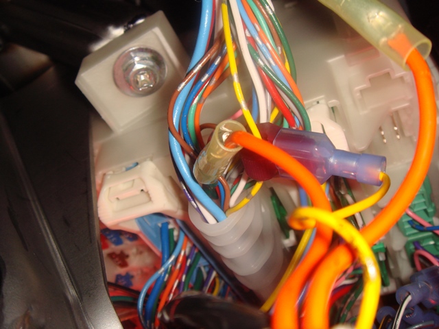
I start with the USDM socket/connector pictures,
notice there is only 3 wires that is for controlling the adjustment of the mirror only.
Then I simply cut the wire from the USDM connector (harness that goes into the car), but I let the USDM connector from the mirror side uncut so I can sell the USDM mirror assy
I then insert the cut wire into the molex pin, after that I test it by plugging it into the JDM mirror molex connector (the molex connector that I bought separately), turn out everything is ok, the mirror adjust correctly. (up down and side movement ok).
after that I took out the old USDM mirror and install the JDM mirror (3 mounting bolt).
After this then I got surprise !
turn out the Molex connector that I used are way too big to fit inside the hole opening to where you route the wire from the mirror...
so I hurry up and go to Fry's to find different Molex connector.
and because I am too lazy to reconnect wire to pin, I decide to just bought a PC power supply extension Molex and wire kit, so I can just cut the cable and soldered it to my previous wiring...
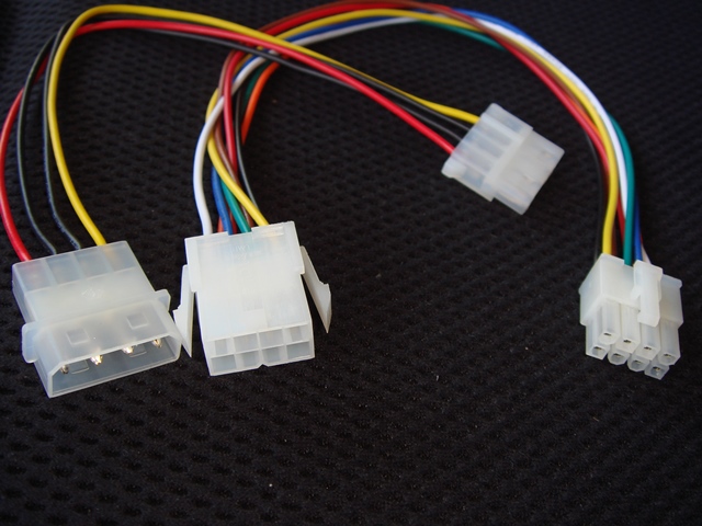
Here are the smaller PC Power Supply extension Molex that fit the hole in the door.
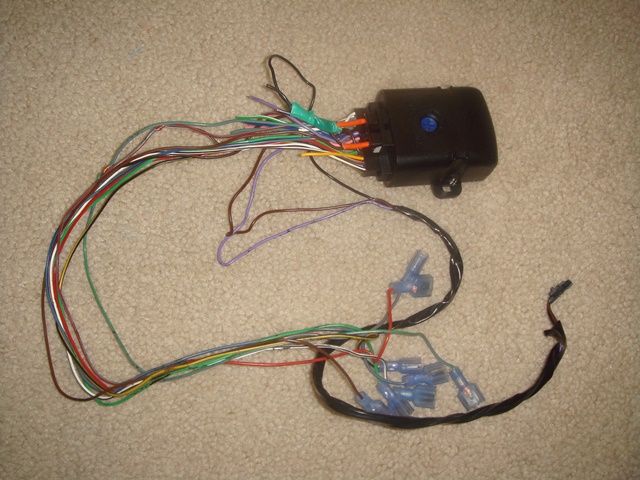
Notice I bought 2 different Molex because I am using a 9 wire connection,
so I need 3 pin/wire for the mirror control movement and another 6 pin/wire for other function (folding, led blinker, heater).
here are the pictures of the PC Power supply Molex:
and here are the pictures after I connect them all:
Oh, yesterday I thought that I manage to broke 1 wire for Locking the door using the door switch when I jam my other wire though the rubber boots...
Turn Out, I did NOT broke any cable,
the reason why I can NOT lock the door using the door switch was because I try to do it while the door itself is OPEN and the car key is in ON position... so this is just a safety system to prevent people from locking their self out while engine is running...
The good news is because I thought I broke this 1 wire,
it force me to trace all the wiring including the damn KARR Alarm wiring.
While I was tracing this wiring, I decide to just took out all the KARR Alarm wiring and all their Tapping connector because it really is UGLY
and I worried that those tapping connector might be the reason one wire broke...
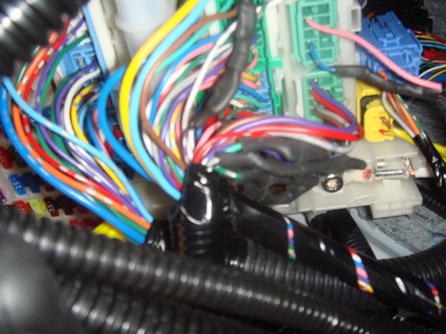
Here are the pictures of all the tapping connector from DAMN KARR alarm:
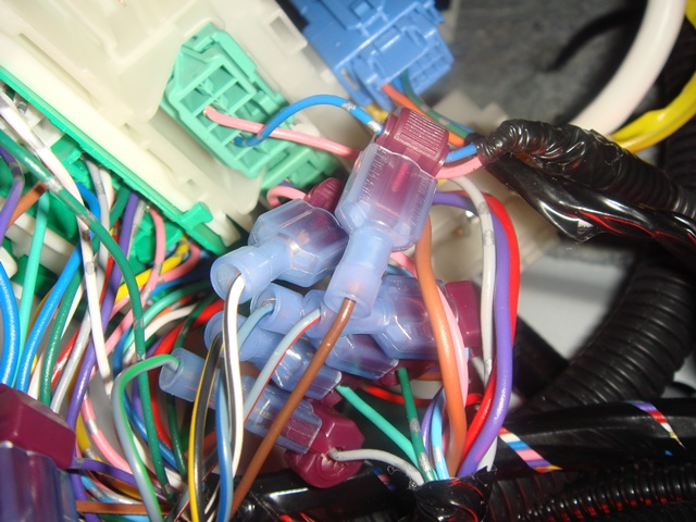
Here are the starter kill tapping of that DAMN KARR ALARM:
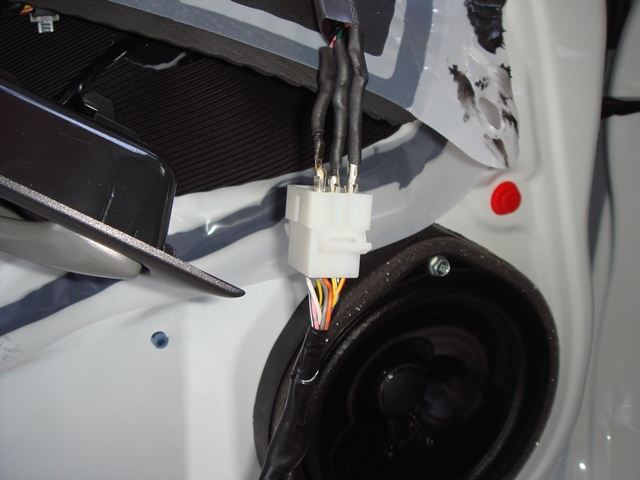
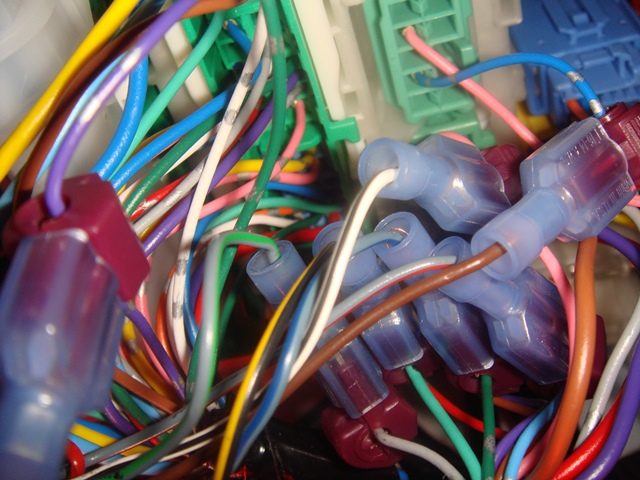
and here are the pictures AFTER I took out all those tapping connector, I then CUT the wire, and then resoldered them with extension wire, then I shrink wrap them.
Notice how cleaner it is:
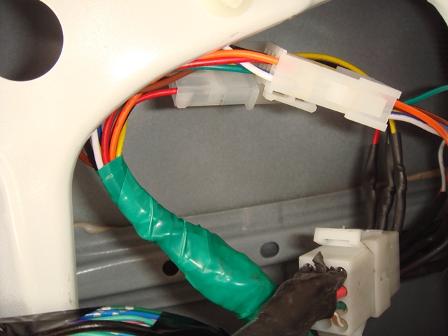
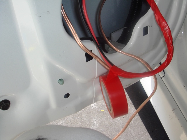
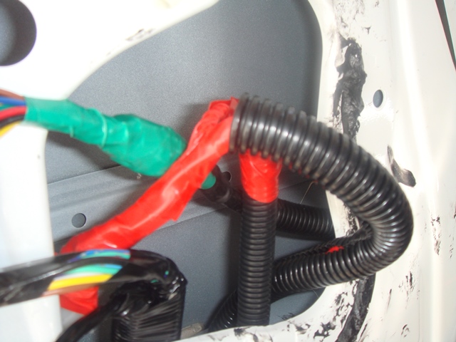
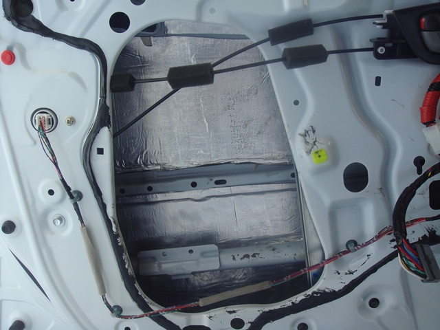
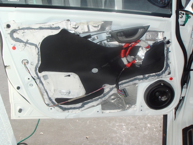
Then I move my attention inside the door, and start by putting electrical isolation tape on the wiring:
on the picture below, notice the uncovered speaker wire?
yes that is the 14 AWG speaker wire that I prepared for future MidBass Speaker upgrade. it is currently not connected to the speaker nor to the factory amplifier...
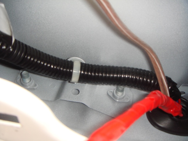
Then for extra protection I cover those wire with the Black Plastic Wire hose/tube and then I zip tied them to the factory original wiring and make sure it is out of the way when the window rolled down:
Oh, I also want to add that all the wire connection are SOLDERED to make sure it have perfect contact, even the ground wiring that are CRIMPED were soldered to the crimp connector to make sure the connection is perfect:
Notice on picture above there are 2 ground wire connected to that crimp connector, 1 ground for LED Blinker, 1 ground for Mirror Heater Element.
I have not connect the positive mirror heater element though cause I want to do it together (parallel connection) with the Right/Passenger door mirror, that mean I have to wait since I had not install the right/passenger door mirror...
I also had not connect the folding connection because I had not install my JDM CR-V backlighted mirror switch, this because I want to wait until I bought the JDM auto folding and auto tilting wiring from Japan, so I don't have to open the dashboard panel twice....
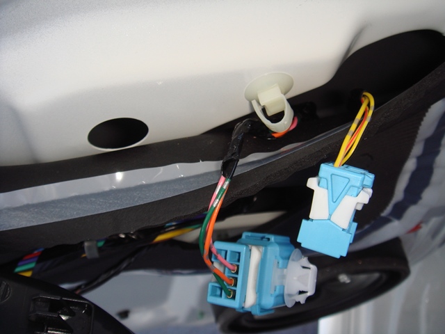
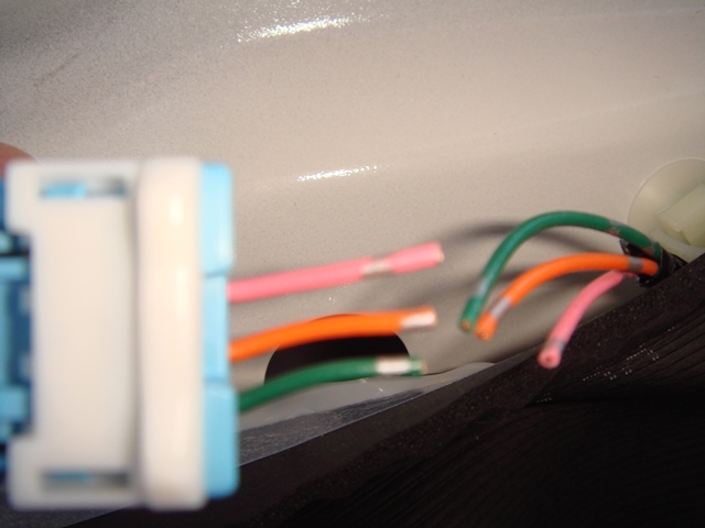
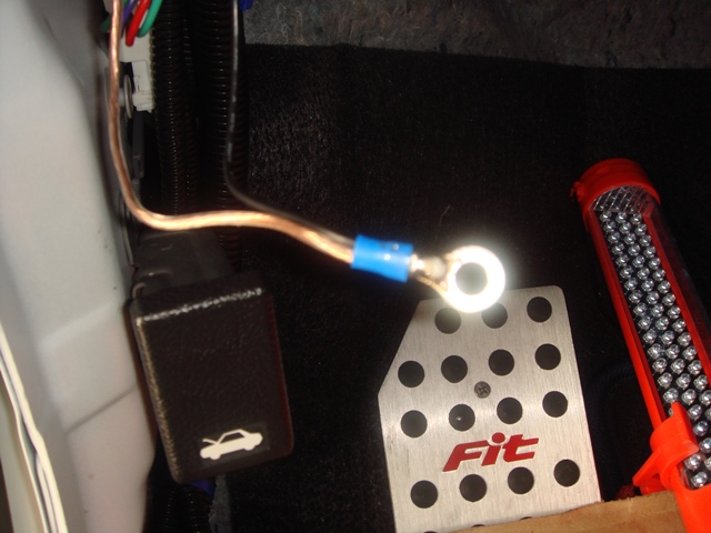
but I did connect the LED mirror blinker to the wiring near the fusebox.
I know which wire to connect from the thread by Niko3257,
but here I take picture again so people can get clearer pictures on which wire to tap/connect:
Ok, on pictures above, notice the BLUE wire coming out from fuse box that is connected (but not soldered yet) with the green wire,
yes, that BLUE wire is the (+) wire for LEFT Blinker.
the green wire is just the wire I use to connect to my JDM LED light,
so never mind that, just focus on the blue wire.
I use the same ground as used by Niko3257,
notice that the I also cover the ground wire with the black wiring hose/loom, but this is more for cosmetic purposes as ground wire don't really need to be protected
Tomorrow I will start doing the Sound Dampening (phase 1) using CLD tiles on the left door, after that finished then I can start working on the right/passenger door).
in the future I will buy MLV to further sound block the door...
but for now, I will just use CLD tiles (this CLD tiles had been bought since 3 months ago, but I was too lazy to do it
the cld tiles is GT Mat Ultra 80.
I skip the door panel opening part because so many people had cover it.
I start with the USDM socket/connector pictures,
notice there is only 3 wires that is for controlling the adjustment of the mirror only.
Then I simply cut the wire from the USDM connector (harness that goes into the car), but I let the USDM connector from the mirror side uncut so I can sell the USDM mirror assy
I then insert the cut wire into the molex pin, after that I test it by plugging it into the JDM mirror molex connector (the molex connector that I bought separately), turn out everything is ok, the mirror adjust correctly. (up down and side movement ok).
after that I took out the old USDM mirror and install the JDM mirror (3 mounting bolt).
After this then I got surprise !
turn out the Molex connector that I used are way too big to fit inside the hole opening to where you route the wire from the mirror...
so I hurry up and go to Fry's to find different Molex connector.
and because I am too lazy to reconnect wire to pin, I decide to just bought a PC power supply extension Molex and wire kit, so I can just cut the cable and soldered it to my previous wiring...
Here are the smaller PC Power Supply extension Molex that fit the hole in the door.
Notice I bought 2 different Molex because I am using a 9 wire connection,
so I need 3 pin/wire for the mirror control movement and another 6 pin/wire for other function (folding, led blinker, heater).
here are the pictures of the PC Power supply Molex:
and here are the pictures after I connect them all:
Oh, yesterday I thought that I manage to broke 1 wire for Locking the door using the door switch when I jam my other wire though the rubber boots...
Turn Out, I did NOT broke any cable,
the reason why I can NOT lock the door using the door switch was because I try to do it while the door itself is OPEN and the car key is in ON position... so this is just a safety system to prevent people from locking their self out while engine is running...
The good news is because I thought I broke this 1 wire,
it force me to trace all the wiring including the damn KARR Alarm wiring.
While I was tracing this wiring, I decide to just took out all the KARR Alarm wiring and all their Tapping connector because it really is UGLY
and I worried that those tapping connector might be the reason one wire broke...
Here are the pictures of all the tapping connector from DAMN KARR alarm:
Here are the starter kill tapping of that DAMN KARR ALARM:
and here are the pictures AFTER I took out all those tapping connector, I then CUT the wire, and then resoldered them with extension wire, then I shrink wrap them.
Notice how cleaner it is:
Then I move my attention inside the door, and start by putting electrical isolation tape on the wiring:
on the picture below, notice the uncovered speaker wire?
yes that is the 14 AWG speaker wire that I prepared for future MidBass Speaker upgrade. it is currently not connected to the speaker nor to the factory amplifier...
Then for extra protection I cover those wire with the Black Plastic Wire hose/tube and then I zip tied them to the factory original wiring and make sure it is out of the way when the window rolled down:
Oh, I also want to add that all the wire connection are SOLDERED to make sure it have perfect contact, even the ground wiring that are CRIMPED were soldered to the crimp connector to make sure the connection is perfect:
Notice on picture above there are 2 ground wire connected to that crimp connector, 1 ground for LED Blinker, 1 ground for Mirror Heater Element.
I have not connect the positive mirror heater element though cause I want to do it together (parallel connection) with the Right/Passenger door mirror, that mean I have to wait since I had not install the right/passenger door mirror...
I also had not connect the folding connection because I had not install my JDM CR-V backlighted mirror switch, this because I want to wait until I bought the JDM auto folding and auto tilting wiring from Japan, so I don't have to open the dashboard panel twice....
but I did connect the LED mirror blinker to the wiring near the fusebox.
I know which wire to connect from the thread by Niko3257,
but here I take picture again so people can get clearer pictures on which wire to tap/connect:
Ok, on pictures above, notice the BLUE wire coming out from fuse box that is connected (but not soldered yet) with the green wire,
yes, that BLUE wire is the (+) wire for LEFT Blinker.
the green wire is just the wire I use to connect to my JDM LED light,
so never mind that, just focus on the blue wire.
I use the same ground as used by Niko3257,
notice that the I also cover the ground wire with the black wiring hose/loom, but this is more for cosmetic purposes as ground wire don't really need to be protected
Tomorrow I will start doing the Sound Dampening (phase 1) using CLD tiles on the left door, after that finished then I can start working on the right/passenger door).
in the future I will buy MLV to further sound block the door...
but for now, I will just use CLD tiles (this CLD tiles had been bought since 3 months ago, but I was too lazy to do it
the cld tiles is GT Mat Ultra 80.
#74
05-24-2013, 02:56 AM
Some extra info for people who plan to upgrade their MidBass Speaker:
I roll the window down, and I measure the distance from the door steel panel (where the speaker plastic spacer/frame mount) to the window, and it is 5cm.
if we measure the distance from the plastic/spacer frame where the speaker actually mount to the window then it is 7cm.
then I measure the maximum distance if we push out the speaker to be as close as possible to the grill (on the door panel),
we could have maximum mounting depth of around 8.5cm !!!
So I better try to find speaker with mounting depth less then 8.5cm or
I will have to drill a hole on the door panel and then make custom grill...
I already have one speaker in my mind, but unfortunately that speaker mounting depth spec is unknown... (it is a midbass from a B&W home speaker
)well, when I am ready to upgrade my car audio, I will just buy that speaker and then think on how to modify the door panel to accept that speaker
you know buy first, think how to fit later hahaha
yeah, I know home speaker were not designed for car environment bla bla bla... but for me, when I already want something, I am going to get it no matter how hard it is, no matter how complicated it is and no matter what the cost will be. if it doesn't fit, I will make it fit !
I only live once, and I intend to live my life to the fullest
#75
05-24-2013, 03:07 AM
Above are the pictures of the KARR Alarm module and wiring,
look how small the module is !!!
and the dealer's finance manager was trying to force me to buy this piece of ******!!! for $800 !!!...
this thing must worth almost nothing cause when I refused to buy,
they don't even bother to took the entire hardware from my car !!!
for $800, I could bought many JDM parts !!!
luckily I don't buy this !!!
feel so good after removing this alarm from my car !
#77
05-24-2013, 10:53 AM
Thanks LoudBang,
I have another idea,
when we lock and unlock our car, the parking light FLASH,
but the Turn Signal LED (including on our mirror), do NOT flash.
so I think we can make our Turn Signal LED Flash when we lock/unlock our car.
All we need to do is add RELAY and Diode.
Connect the Parking Light Positive Wire through Relay as the source power for the LED Turn Signal Light,
Control the Relay On or Off position using Ignition Wire,
meaning when the car is ON, the Relay will BLOCK the power from Parking Light to enter LED Turn Signal.
But when the car is OFF, the Relay will close the switch and let the power from the Parking Light to enter the LED Turn Signal
Now we had to use DIODE in line with each wire from relay output connected to the Left and Right Turn Signal LED,
this is to prevent Right turn signal to turn on when we only want to turn on Left turn signal and vice versa
because remember both of them were joined by just one relay (unless you want to use 2 separate relays of course).
If we don't put Diode, than when you turn on just Left (or Right) turn signal, both Turn Signal with turn on like Hazard Light blinking mode !
Oh, that diode is also very important in preventing the Parking Light to Blink when you turn your turn signal on
The only weakness to this circuit is if we turn on the Parking Light while the car is turn off, then both/all LED Turn Signal Light will be On (not blinking)...
but then again it is very rare to have the car turn off, yet we still let the parking light on and we lock/unlock the car...
I think I want to do this !
ps: the key here is using the relay to block the power when the relay had positive input into it's trigger side,
the opposite of what we usually use relay in Horn or Head Light application !
Last edited by BMW ALPINA; 05-24-2013 at 11:41 AM.
#79
05-24-2013, 12:05 PM
Thanks for your kind words Wafulz,
by the way, I just sent you a PM,
I need your help
Thanks Again
by the way, I just sent you a PM,
I need your help
Thanks Again
#80
05-24-2013, 09:45 PM
Sound deadening the Driver/Left Door with CLD Tiles,
I cover at least 90% of the area INSIDE the door !
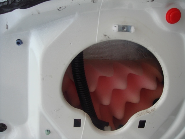
After that I put Acoustic Foam BEHIND the Speaker Opening so to absorb unwanted resonance
I glue the foam using 3M Ultra 77 Glue,
I also make sure the foam only cover half the height of the speaker opening so it won't interfere with the window rolled down.
Then every large hole opening were covered with this Aluminum plate,
that I cut from a baking plate hahaha
notice one of the plate is still intact the other is what left of it
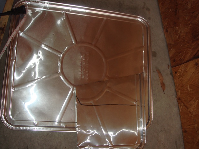
Oh, I forgot, I attached the backing plate using that 3M CALK Strip that I mention in this thread before, That 3M Calk Strip is also good to cover little gap if needed to further sealed the door !
Then on top of the aluminum plate, I cover the front side/plate of the door with more CLD tiles...but this time
I only manage to cover probably around 70% of the front door plate area
because at first I worry the door panel might not goes back in easily if it is too thick,
I plan to buy MLV later, and I am pretty sure there is enough space to add MLV layer on top of the CLD tiles, but I will do this only after I bought my Mid Bass speaker, so I don't have to open and close the door panel too often... the clip's are easy to broke, I already broke 1 MOUNTING for the clip... but it still work fine...
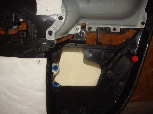
After that I recover the CLD tiles with factory original plastic covering,
but I had to cut the center square piece since it is molded as a cube...
you know what I mean when you open a brand new door later
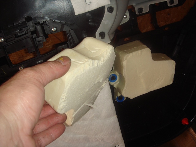
Finally, I had to cut the foam, this foam is also cube that suppose to go on top of the plastic pieces that I am talking above...
this foam is attached to the door panel...
I cut about 1/2 the height and it's fine now
then I put the door cover panel back, and test the sound of my speaker,...
it does have a little bit more bass and the midrange is less harsh now
I haven't drive it on the street, so I would not know how much quieter this one door will be..., but it took me half a day just to do one door, since I am doing everything so carefully... I need a break...
will continue doing the right door after memorial day holiday
I cover at least 90% of the area INSIDE the door !
After that I put Acoustic Foam BEHIND the Speaker Opening so to absorb unwanted resonance
I glue the foam using 3M Ultra 77 Glue,
I also make sure the foam only cover half the height of the speaker opening so it won't interfere with the window rolled down.
Then every large hole opening were covered with this Aluminum plate,
that I cut from a baking plate hahaha
notice one of the plate is still intact the other is what left of it
Oh, I forgot, I attached the backing plate using that 3M CALK Strip that I mention in this thread before, That 3M Calk Strip is also good to cover little gap if needed to further sealed the door !
Then on top of the aluminum plate, I cover the front side/plate of the door with more CLD tiles...but this time
I only manage to cover probably around 70% of the front door plate area
because at first I worry the door panel might not goes back in easily if it is too thick,
I plan to buy MLV later, and I am pretty sure there is enough space to add MLV layer on top of the CLD tiles, but I will do this only after I bought my Mid Bass speaker, so I don't have to open and close the door panel too often... the clip's are easy to broke, I already broke 1 MOUNTING for the clip... but it still work fine...
After that I recover the CLD tiles with factory original plastic covering,
but I had to cut the center square piece since it is molded as a cube...
you know what I mean when you open a brand new door later
Finally, I had to cut the foam, this foam is also cube that suppose to go on top of the plastic pieces that I am talking above...
this foam is attached to the door panel...
I cut about 1/2 the height and it's fine now
then I put the door cover panel back, and test the sound of my speaker,...
it does have a little bit more bass and the midrange is less harsh now
I haven't drive it on the street, so I would not know how much quieter this one door will be..., but it took me half a day just to do one door, since I am doing everything so carefully... I need a break...
will continue doing the right door after memorial day holiday
Last edited by BMW ALPINA; 05-24-2013 at 09:48 PM.