DIY Valve Clearance Check
#21
 06-29-2014, 01:22 PM


i didn't notice as i adjusted each cylinder as the number came up when there was play in both sets of valves.
you can answer your question by roataing the engine clockwise with the valve cover off. look at the intake valves for #2 if they are closing and #3 is closing at the same time then both might be at TDC at the same time. if so then both 2 & 3 would have lash clearence and could be adjusted at the same time...but i bet there is some timing overlap and this is not the case.
most people just stick to adjusting one cylinder at a time to lessen confusion.......
GD
#22
07-10-2014, 01:23 AM

I'm making this DIY for all of you that don't have a service manual or don't like the pictures in the service manual. For all of you that don't have the service manual, I recommend you get it or ensure that you have access to it. You can get a CD copy on eBay for $20 or a print copy for $85. Cheap insurance incase you really foul something up!
Items needed to do this procedure:
*Beverage of choice (but as a safety professional, I cannot condone drinking said beverage by chemicals [engine oil]). Don't ask, don't tell!
*L15A7 engine
*Set of feeler gauges (see below for sizes)
*Tube of Hondabond (or equivalent gasket maker)
*Phillips screwdriver
*Small flathead screwdriver
*10mm open ended wrench
*19mm extended socket
*10mm extended socket
*12mm extended socket
*Socket extension (where appropriate)
*Socket wrench(es) (likely a 3/8" and a 1/2" depending on your tools)
*Pliers (needle nose and flat jaw recommended)
OPTIONAL: 12341-RB0-003 Honda Valve Cover Gasket (only needed to reassurance or if you plan on replacing it - unless the original is damaged, you should be able to reuse it)
**DISCLAIMER**: As with any DIY on any internet forum, I cannot be held responsible for omissions or errors that may contribute to you not being able to complete this job nor am I responsible for any damages caused as a result of this maintenance procedure. If you are unwilling, unable, or not very competent in maintenance, you are discouraged from performing this procedure.
The if this is your first time performing this procedure, it'll likely take you 2-3 hours to do. After you've done it once, though, it should take you not much more than an hour for tear down, measurements and adjustments, and reassembly. Also keep in mind that your vehicle will need to be "cold" (meaning at ambient temperature and the engine has not been run in 6-8 hours). Also keep in mind that your vehicle will essentially not be drivable during this procedure, so if you forgot a tool or there is an emergency, you might be boned unless you have access to another vehicle (recommended).
Onwards to tear down:
First, turn the wheels all the way to the right (as a reminder, don't turn on the car for this - you should be able to do it with some muscle). This will allow you to not have to remove the wheel and easily allow access to the crank to spin the engine to the position you need it.
Then, open the bonnet (hood). Stare in mild admiration at L15A7.

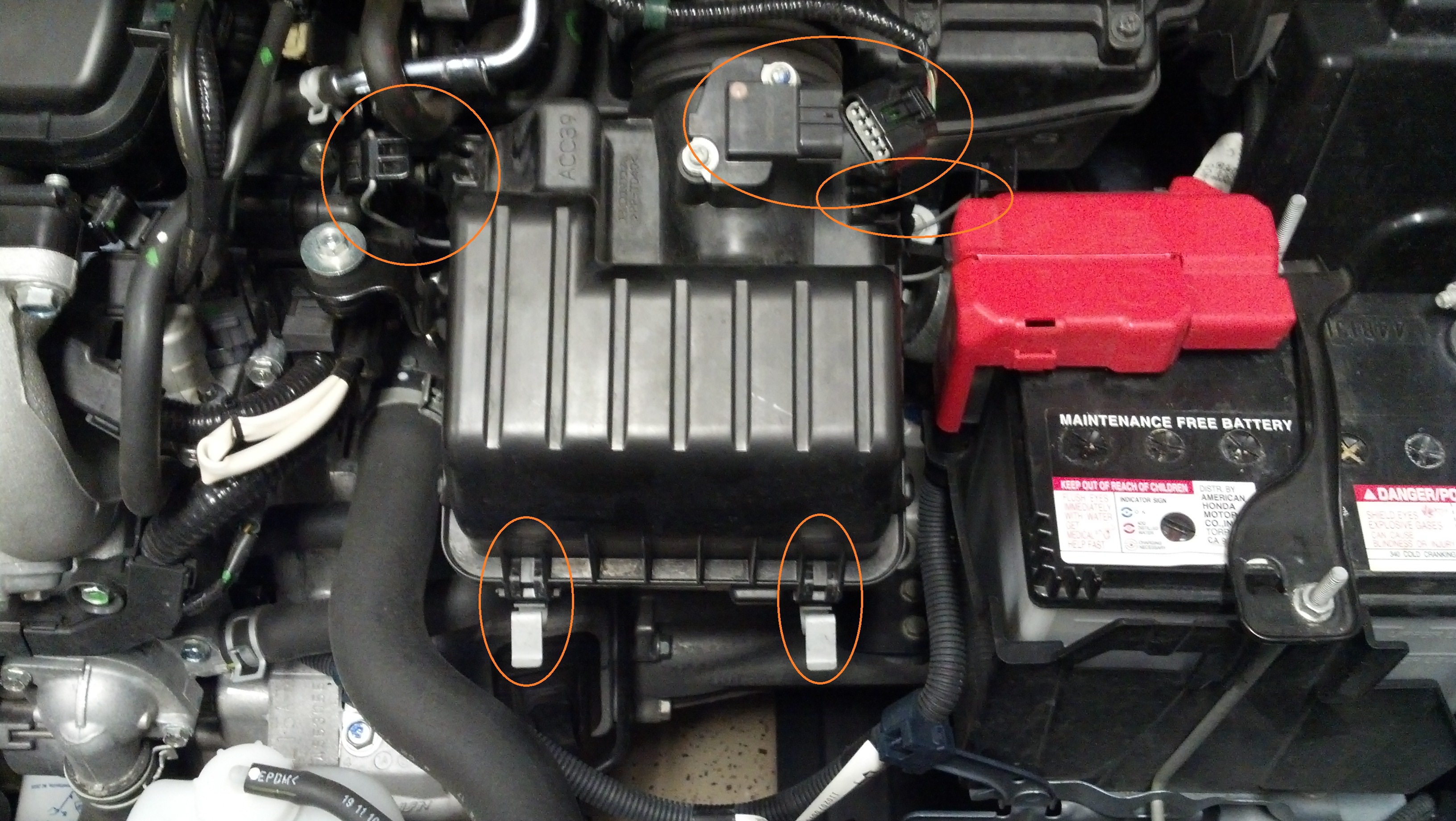
Remove the clips to the air filter and the cable going to the MAF and remove the air filter box and filter.

Disconnect the battery connections and holder bracket by using a 10mm extended socket. You will not need to completely unbolt the holder bracket since the hangers can be undone by sliding them out from underneath the battery mount. Remove battery, battery tray, and holder bracket.

Loosen clamp holding the rest of the airbox to the throttle body. Don't worry about it sliding back - Honda designed a holder of sorts to keep it from sliding back. Make sure to only loosen - do not unscrew completely.

Then remove the two 10mm bolts holding the airbox to the engine and transmission and undo the green wire holder. Carefully slide/wiggle the assembly away from the throttle body. Then remove metal vacuum tube (circled in red, out of view) away from airbox using pliers to relieve pressure off the rubber gasket. Then remove assembly from the area.

Remove the four (4) 12mm bolts from the throttle body. Take care not to look the metal brackets on the back and front side of the throttle body. Carefully push throttle body out of way.

Disconnect the two wires shown.

Remove the five (5) 12mm bolts holding the plastic manifold to the metal one. Remove metal bracket behind plastic manifold.


Then remove the two (2) 10mm bolts from behind the plastic manifold.

Remove the last 12mm bolt on the side of the plastic manifold and the vacuum tube from the valve cover. There is also a tube connected to the backside of the plastic manifold that will need to be undone from a holding bracket. You do not need to remove the tube from the plastic manifold, but you can simply place over to the side.

Carefully disconnect the coil pack connectors, release the left side bracket and slide the wire assembly out of the way.


Then remove the eight (8) 10mm bolts holding the valve cover. Remove cover.

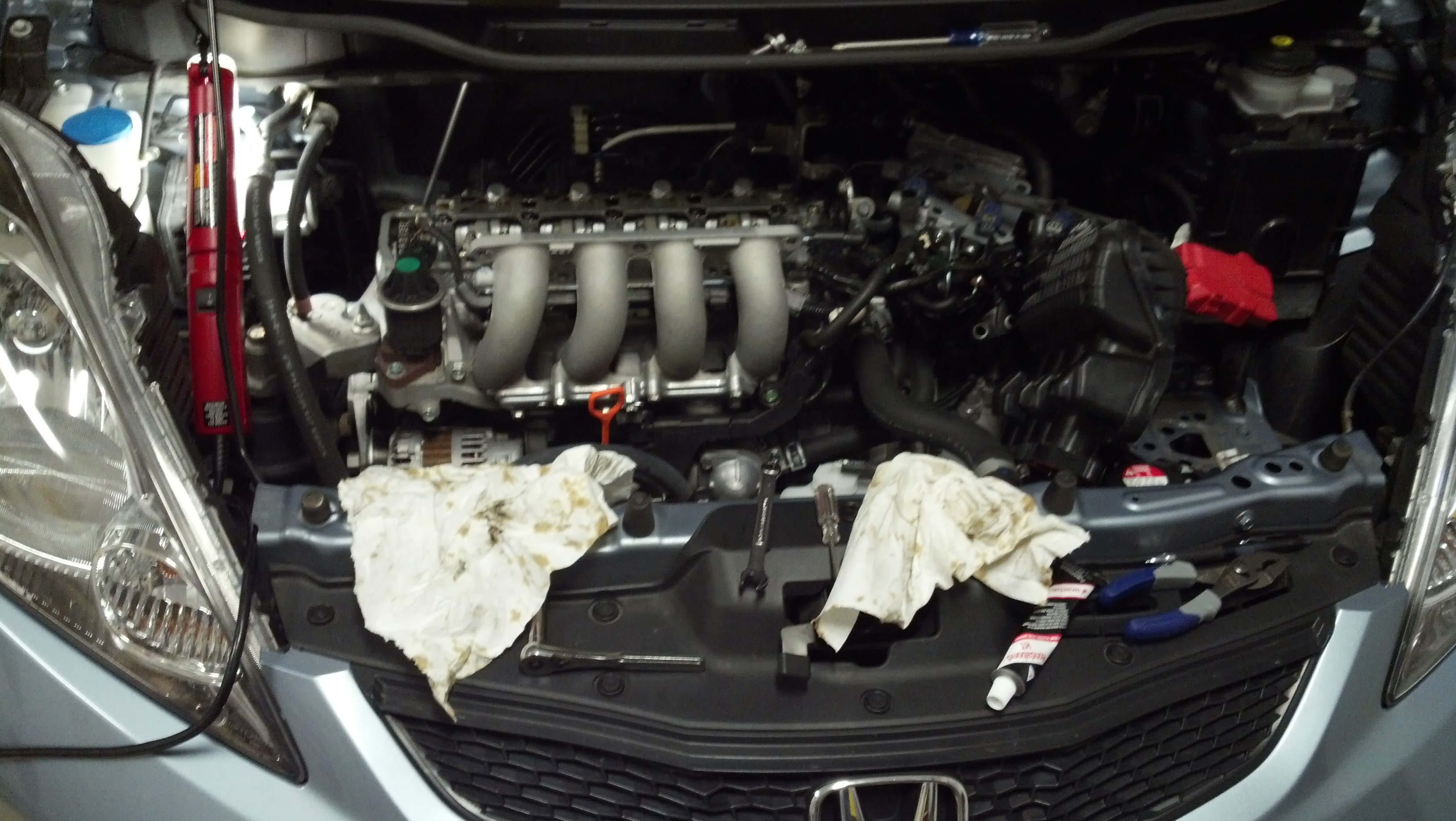
All items removed for check:

You are now presented with the inner workings of the L15A7. Note cylinder numbers and intake and exhaust valves (but you should already know that).

Notice the cam chain area and the marking that indicate top dead center (TDC) for the cylinder number indicated. The photo below shows you that I was close to cylinder #2 TDC. The line should be as close to flush (and horizontal) with the top of the head.

Now insert the 19mm socket with appropriate extension into to the perforated hole in the passenger side front wheel well to turn the crank. Make sure to only turn the crank clockwise! If you are good (read: tall), you can turn the crank and see where your marking are without help from a friend. Position to the cylinder of choice and then check that cylinder, both intake and exhaust, for clearance.

Valve Clearance (cold)
Intake 0.15-0.19 mm (0.006-0.007 in)
Exhaust 0.26-0.30 mm (0.010-0.012 in)
Remember when checking clearances, that you should feel a slight resistance and should feel a slight vibration as you slide the gauge back and fourth. This indicates that you are at the selected thickness. Take care not to bend the gauge while checking the measurements as it can lead to incorrect measurements/adjustments. For more information on doing adjustments refer to this page. Adjustments are completed by using your 100 open ended wrench and a flat head screwdriver to adjust the gap. Make sure to re-tighten the nut while holding the screw in place during adjustments!
Have fun!

After all cylinders have been checked and adjusted, reassemble in reverse order. Make sure to clean the area that the gasket will come into contact with and to put a dab of Hondabond on the cam seam (front and back) before replacing the valve cover.
Items needed to do this procedure:
*Beverage of choice (but as a safety professional, I cannot condone drinking said beverage by chemicals [engine oil]). Don't ask, don't tell!
*L15A7 engine
*Set of feeler gauges (see below for sizes)
*Tube of Hondabond (or equivalent gasket maker)
*Phillips screwdriver
*Small flathead screwdriver
*10mm open ended wrench
*19mm extended socket
*10mm extended socket
*12mm extended socket
*Socket extension (where appropriate)
*Socket wrench(es) (likely a 3/8" and a 1/2" depending on your tools)
*Pliers (needle nose and flat jaw recommended)
OPTIONAL: 12341-RB0-003 Honda Valve Cover Gasket (only needed to reassurance or if you plan on replacing it - unless the original is damaged, you should be able to reuse it)
**DISCLAIMER**: As with any DIY on any internet forum, I cannot be held responsible for omissions or errors that may contribute to you not being able to complete this job nor am I responsible for any damages caused as a result of this maintenance procedure. If you are unwilling, unable, or not very competent in maintenance, you are discouraged from performing this procedure.
The if this is your first time performing this procedure, it'll likely take you 2-3 hours to do. After you've done it once, though, it should take you not much more than an hour for tear down, measurements and adjustments, and reassembly. Also keep in mind that your vehicle will need to be "cold" (meaning at ambient temperature and the engine has not been run in 6-8 hours). Also keep in mind that your vehicle will essentially not be drivable during this procedure, so if you forgot a tool or there is an emergency, you might be boned unless you have access to another vehicle (recommended).
Onwards to tear down:
First, turn the wheels all the way to the right (as a reminder, don't turn on the car for this - you should be able to do it with some muscle). This will allow you to not have to remove the wheel and easily allow access to the crank to spin the engine to the position you need it.
Then, open the bonnet (hood). Stare in mild admiration at L15A7.
Remove the clips to the air filter and the cable going to the MAF and remove the air filter box and filter.
Disconnect the battery connections and holder bracket by using a 10mm extended socket. You will not need to completely unbolt the holder bracket since the hangers can be undone by sliding them out from underneath the battery mount. Remove battery, battery tray, and holder bracket.
Loosen clamp holding the rest of the airbox to the throttle body. Don't worry about it sliding back - Honda designed a holder of sorts to keep it from sliding back. Make sure to only loosen - do not unscrew completely.
Then remove the two 10mm bolts holding the airbox to the engine and transmission and undo the green wire holder. Carefully slide/wiggle the assembly away from the throttle body. Then remove metal vacuum tube (circled in red, out of view) away from airbox using pliers to relieve pressure off the rubber gasket. Then remove assembly from the area.
Remove the four (4) 12mm bolts from the throttle body. Take care not to look the metal brackets on the back and front side of the throttle body. Carefully push throttle body out of way.
Disconnect the two wires shown.
Remove the five (5) 12mm bolts holding the plastic manifold to the metal one. Remove metal bracket behind plastic manifold.
Then remove the two (2) 10mm bolts from behind the plastic manifold.
Remove the last 12mm bolt on the side of the plastic manifold and the vacuum tube from the valve cover. There is also a tube connected to the backside of the plastic manifold that will need to be undone from a holding bracket. You do not need to remove the tube from the plastic manifold, but you can simply place over to the side.
Carefully disconnect the coil pack connectors, release the left side bracket and slide the wire assembly out of the way.
Then remove the eight (8) 10mm bolts holding the valve cover. Remove cover.
All items removed for check:
You are now presented with the inner workings of the L15A7. Note cylinder numbers and intake and exhaust valves (but you should already know that).
Notice the cam chain area and the marking that indicate top dead center (TDC) for the cylinder number indicated. The photo below shows you that I was close to cylinder #2 TDC. The line should be as close to flush (and horizontal) with the top of the head.
Now insert the 19mm socket with appropriate extension into to the perforated hole in the passenger side front wheel well to turn the crank. Make sure to only turn the crank clockwise! If you are good (read: tall), you can turn the crank and see where your marking are without help from a friend. Position to the cylinder of choice and then check that cylinder, both intake and exhaust, for clearance.
Valve Clearance (cold)
Intake 0.15-0.19 mm (0.006-0.007 in)
Exhaust 0.26-0.30 mm (0.010-0.012 in)
Remember when checking clearances, that you should feel a slight resistance and should feel a slight vibration as you slide the gauge back and fourth. This indicates that you are at the selected thickness. Take care not to bend the gauge while checking the measurements as it can lead to incorrect measurements/adjustments. For more information on doing adjustments refer to this page. Adjustments are completed by using your 100 open ended wrench and a flat head screwdriver to adjust the gap. Make sure to re-tighten the nut while holding the screw in place during adjustments!
Have fun!
After all cylinders have been checked and adjusted, reassemble in reverse order. Make sure to clean the area that the gasket will come into contact with and to put a dab of Hondabond on the cam seam (front and back) before replacing the valve cover.
Just to double check when doing tdc for example cylinder 1, then intake and exhaust can both be measured for both sides ex an in for #1 tdc ?

#25
07-15-2014, 03:51 PM
correct size
hey what feeler gauge did you use? mine has the 0.010 - 0.012 but, not the exact 0.006 - 0.007 only 0.006-0.008 and 0.006 -0.005 would like to on the money with measurements .... Or you know where to get single valve lash feeler stick for that size?

#28
11-07-2015, 11:04 PM
Wow, appreciate all the info and glad I was able to save $500 on dealer price for valve check/adjustment and sparks. Took forever though, like 4 plus hours. Plus one of the head cover bolts tore on me. Most of my valves were reasonable, the intakes were generally tight while the exhaust were within spec strangely enough. Even after all my reading I was surprised how much stuff I had to move just to get to the valves...Cheers

#30
11-11-2015, 08:36 PM
I did my best to try to redo the pics for the original post while I did my valve adjustment. Hope it helps. I followed the original post for my first valve adjustment and now I don't even have to refer to it anymore. I skipped the intake removal since I no longer have the stock intake and the pic wouldnt make sense.
I'm making this DIY for all of you that don't have a service manual or don't like the pictures in the service manual. For all of you that don't have the service manual, I recommend you get it or ensure that you have access to it. You can get a CD copy on eBay for $20 or a print copy for $85. Cheap insurance incase you really foul something up!
Items needed to do this procedure:
*Beverage of choice (but as a safety professional, I cannot condone drinking said beverage by chemicals [engine oil]). Don't ask, don't tell!
*L15A7 engine
*Set of feeler gauges (see below for sizes)
*Tube of Hondabond (or equivalent gasket maker)
*Phillips screwdriver
*Small flathead screwdriver
*10mm open ended wrench
*19mm extended socket
*10mm extended socket
*12mm extended socket
*Socket extension (where appropriate)
*Socket wrench(es) (likely a 3/8" and a 1/2" depending on your tools)
*Pliers (needle nose and flat jaw recommended)
OPTIONAL: 12341-RB0-003 Honda Valve Cover Gasket (only needed to reassurance or if you plan on replacing it - unless the original is damaged, you should be able to reuse it)
**DISCLAIMER**: As with any DIY on any internet forum, I cannot be held responsible for omissions or errors that may contribute to you not being able to complete this job nor am I responsible for any damages caused as a result of this maintenance procedure. If you are unwilling, unable, or not very competent in maintenance, you are discouraged from performing this procedure.
The if this is your first time performing this procedure, it'll likely take you 2-3 hours to do. After you've done it once, though, it should take you not much more than an hour for tear down, measurements and adjustments, and reassembly. Also keep in mind that your vehicle will need to be "cold" (meaning at ambient temperature and the engine has not been run in 6-8 hours). Also keep in mind that your vehicle will essentially not be drivable during this procedure, so if you forgot a tool or there is an emergency, you might be boned unless you have access to another vehicle (recommended).
Onwards to tear down:
First, turn the wheels all the way to the right (as a reminder, don't turn on the car for this - you should be able to do it with some muscle). This will allow you to not have to remove the wheel and easily allow access to the crank to spin the engine to the position you need it.
Then, open the bonnet (hood). Stare in mild admiration at L15A7.

Remove the clips to the air filter and the cable going to the MAF and remove the air filter box and filter.
Disconnect the battery connections and holder bracket by using a 10mm extended socket. You will not need to completely unbolt the holder bracket since the hangers can be undone by sliding them out from underneath the battery mount. Remove battery, battery tray, and holder bracket.

Loosen clamp holding the rest of the airbox to the throttle body. Don't worry about it sliding back - Honda designed a holder of sorts to keep it from sliding back. Make sure to only loosen - do not unscrew completely.

Then remove the two 10mm bolts holding the airbox to the engine and transmission and undo the green wire holder. Carefully slide/wiggle the assembly away from the throttle body. Then remove metal vacuum tube (circled in red, out of view) away from airbox using pliers to relieve pressure off the rubber gasket. Then remove assembly from the area.

Remove the four (4) 12mm bolts from the throttle body. Take care not to look the metal brackets on the back and front side of the throttle body. Carefully push throttle body out of way.

Disconnect the two wires shown.

Remove the five (5) 12mm bolts holding the plastic manifold to the metal one. Remove metal bracket behind plastic manifold.

Then remove the two (2) 10mm bolts from behind the plastic manifold.

Remove the last 12mm bolt on the side of the plastic manifold and the vacuum tube from the valve cover. There is also a tube connected to the backside of the plastic manifold that will need to be undone from a holding bracket. You do not need to remove the tube from the plastic manifold, but you can simply place over to the side.


Carefully disconnect the coil pack connectors, release the left side bracket and slide the wire assembly out of the way.

Then remove the eight (8) 10mm bolts holding the valve cover. Remove cover.

All items removed for check:

You are now presented with the inner workings of the L15A7. Note cylinder numbers and intake and exhaust valves (but you should already know that).

Notice the cam chain area and the marking that indicate top dead center (TDC) for the cylinder number indicated. The photo below shows you that I was close to cylinder #2 TDC. The line should be as close to flush (and horizontal) with the top of the head.
!!!!!!!!!!!!///////////This is TDC for cylinder #1//////////////!!!!!!!!!!

Now insert the 19mm socket with appropriate extension into to the perforated hole in the passenger side front wheel well to turn the crank. Make sure to only turn the crank clockwise! If you are good (read: tall), you can turn the crank and see where your marking are without help from a friend. Position to the cylinder of choice and then check that cylinder, both intake and exhaust, for clearance.
sorry terrible picture lol


Valve Clearance (cold)
Intake 0.15-0.19 mm (0.006-0.007 in)
Exhaust 0.26-0.30 mm (0.010-0.012 in)
Remember when checking clearances, that you should feel a slight resistance and should feel a slight vibration as you slide the gauge back and fourth. This indicates that you are at the selected thickness. Take care not to bend the gauge while checking the measurements as it can lead to incorrect measurements/adjustments. For more information on doing adjustments refer to this page. Adjustments are completed by using your 100 open ended wrench and a flat head screwdriver to adjust the gap. Make sure to re-tighten the nut while holding the screw in place during adjustments!
Ignore my feeler gauge. I have different valve lash specs for the bisimoto cam.

Have fun!
After all cylinders have been checked and adjusted, reassemble in reverse order. Make sure to clean the area that the gasket will come into contact with and to put a dab of Hondabond on the cam seam (front and back) before replacing the valve cover.

Items needed to do this procedure:
*Beverage of choice (but as a safety professional, I cannot condone drinking said beverage by chemicals [engine oil]). Don't ask, don't tell!
*L15A7 engine
*Set of feeler gauges (see below for sizes)
*Tube of Hondabond (or equivalent gasket maker)
*Phillips screwdriver
*Small flathead screwdriver
*10mm open ended wrench
*19mm extended socket
*10mm extended socket
*12mm extended socket
*Socket extension (where appropriate)
*Socket wrench(es) (likely a 3/8" and a 1/2" depending on your tools)
*Pliers (needle nose and flat jaw recommended)
OPTIONAL: 12341-RB0-003 Honda Valve Cover Gasket (only needed to reassurance or if you plan on replacing it - unless the original is damaged, you should be able to reuse it)
**DISCLAIMER**: As with any DIY on any internet forum, I cannot be held responsible for omissions or errors that may contribute to you not being able to complete this job nor am I responsible for any damages caused as a result of this maintenance procedure. If you are unwilling, unable, or not very competent in maintenance, you are discouraged from performing this procedure.
The if this is your first time performing this procedure, it'll likely take you 2-3 hours to do. After you've done it once, though, it should take you not much more than an hour for tear down, measurements and adjustments, and reassembly. Also keep in mind that your vehicle will need to be "cold" (meaning at ambient temperature and the engine has not been run in 6-8 hours). Also keep in mind that your vehicle will essentially not be drivable during this procedure, so if you forgot a tool or there is an emergency, you might be boned unless you have access to another vehicle (recommended).
Onwards to tear down:
First, turn the wheels all the way to the right (as a reminder, don't turn on the car for this - you should be able to do it with some muscle). This will allow you to not have to remove the wheel and easily allow access to the crank to spin the engine to the position you need it.
Then, open the bonnet (hood). Stare in mild admiration at L15A7.
Remove the clips to the air filter and the cable going to the MAF and remove the air filter box and filter.
Disconnect the battery connections and holder bracket by using a 10mm extended socket. You will not need to completely unbolt the holder bracket since the hangers can be undone by sliding them out from underneath the battery mount. Remove battery, battery tray, and holder bracket.
Loosen clamp holding the rest of the airbox to the throttle body. Don't worry about it sliding back - Honda designed a holder of sorts to keep it from sliding back. Make sure to only loosen - do not unscrew completely.
Then remove the two 10mm bolts holding the airbox to the engine and transmission and undo the green wire holder. Carefully slide/wiggle the assembly away from the throttle body. Then remove metal vacuum tube (circled in red, out of view) away from airbox using pliers to relieve pressure off the rubber gasket. Then remove assembly from the area.
Remove the four (4) 12mm bolts from the throttle body. Take care not to look the metal brackets on the back and front side of the throttle body. Carefully push throttle body out of way.
Disconnect the two wires shown.
Remove the five (5) 12mm bolts holding the plastic manifold to the metal one. Remove metal bracket behind plastic manifold.
Then remove the two (2) 10mm bolts from behind the plastic manifold.
Remove the last 12mm bolt on the side of the plastic manifold and the vacuum tube from the valve cover. There is also a tube connected to the backside of the plastic manifold that will need to be undone from a holding bracket. You do not need to remove the tube from the plastic manifold, but you can simply place over to the side.
Carefully disconnect the coil pack connectors, release the left side bracket and slide the wire assembly out of the way.
Then remove the eight (8) 10mm bolts holding the valve cover. Remove cover.
All items removed for check:
You are now presented with the inner workings of the L15A7. Note cylinder numbers and intake and exhaust valves (but you should already know that).
Notice the cam chain area and the marking that indicate top dead center (TDC) for the cylinder number indicated. The photo below shows you that I was close to cylinder #2 TDC. The line should be as close to flush (and horizontal) with the top of the head.
!!!!!!!!!!!!///////////This is TDC for cylinder #1//////////////!!!!!!!!!!
Now insert the 19mm socket with appropriate extension into to the perforated hole in the passenger side front wheel well to turn the crank. Make sure to only turn the crank clockwise! If you are good (read: tall), you can turn the crank and see where your marking are without help from a friend. Position to the cylinder of choice and then check that cylinder, both intake and exhaust, for clearance.
sorry terrible picture lol
Valve Clearance (cold)
Intake 0.15-0.19 mm (0.006-0.007 in)
Exhaust 0.26-0.30 mm (0.010-0.012 in)
Remember when checking clearances, that you should feel a slight resistance and should feel a slight vibration as you slide the gauge back and fourth. This indicates that you are at the selected thickness. Take care not to bend the gauge while checking the measurements as it can lead to incorrect measurements/adjustments. For more information on doing adjustments refer to this page. Adjustments are completed by using your 100 open ended wrench and a flat head screwdriver to adjust the gap. Make sure to re-tighten the nut while holding the screw in place during adjustments!
Ignore my feeler gauge. I have different valve lash specs for the bisimoto cam.
Have fun!
After all cylinders have been checked and adjusted, reassemble in reverse order. Make sure to clean the area that the gasket will come into contact with and to put a dab of Hondabond on the cam seam (front and back) before replacing the valve cover.
Last edited by 07fit916; 11-11-2015 at 08:40 PM.
#32
11-13-2015, 11:57 PM
Thanks for reposting pics. Glad I did mine but I did find it a lot of work. Bent tip feeler guages are now on the shopping list...Runs quieter, smoother but I did have a plug that wasn't screwes down completely-weird. Keep thinking there has to be an easier way. Anyways, saved me some cash and I learned a bunch. Pretty experienced car guys at work said they wouldnt try to do their valves themselves so it's a cool feeling for a hack like me. Cheers
#33
12-26-2015, 08:42 PM

This was the most excellent tutorial I've ever seen. I used this thread word for word. If this would be the car I drive I would be thankful, seeing how I am giving my 79 year old mother this car after theses adjustments. I bow down with great respect and say thank you. I'm very anal about stuff and these instructions were letter for letter PERFECT!!!! I'm very mechanicaly incline and had no issues. The car is PERFECT. I have total faith she will drive this car to the cars death, or hers. Preferably the prior. I've been a lurker for a while. Now with my 2015 CVT. I will be avid. Thank you all once again for such an INFORMATIVE post. You ALL have my gratitude!!!


#40
02-06-2017, 11:33 PM

exhausts were tight, .009 or so. intakes were loose, .007 or so.
I was impressed the original plugs went the full 100k, didn't look bad at all.
It's a little quieter at idle and I firmly believe I'm getting a bit more power out of it but that's probably an illusion.