When you click on links to various merchants on this site and make a purchase, this can result in this site earning a commission. Affiliate programs and affiliations include, but are not limited to, the eBay Partner Network.
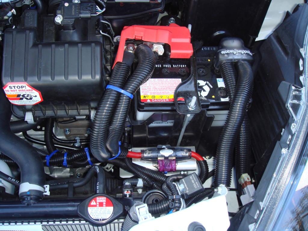
Hi below is the Picture of my Big 3 Wiring + PIAA Horn,
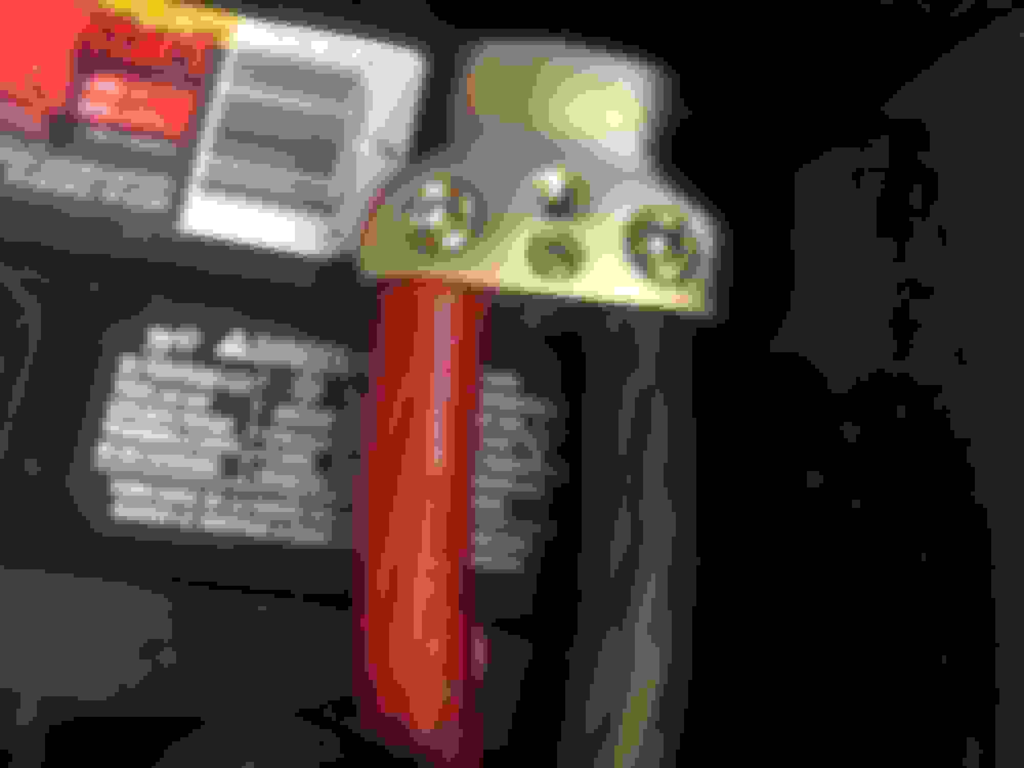
I use Monster Cable 1/0 Gauge Crimpless Terminal to connect a 1/0 Gauge Power Cable on to Alternator Positive Output Terminal.
This is because the Positive Alternator Terminal had a Plastic Shrouding that will NOT accomodate normal (larger size) crimp terminal.
This is the product: http://www.monstercable.com/mpc/productPageMPC.asp?pin=3052�ion=two
I also REMOVE the Factory Positive Wiring that used to connect to the alternator, and I Move it to connect to the Fuse Block, so now both the Factory Positive Wiring and The Direct Big 3 positive wiring are now FUSED for safety.
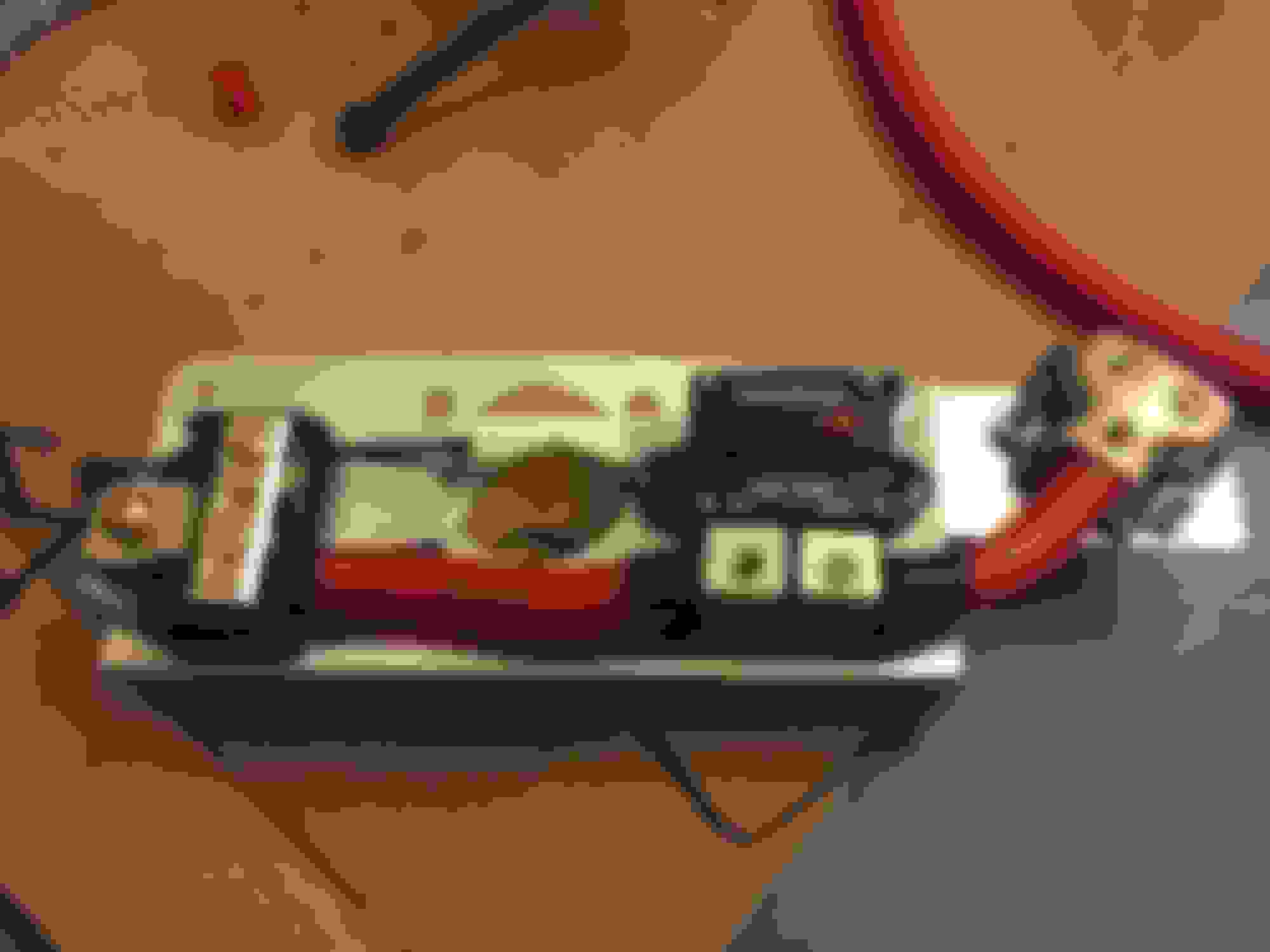
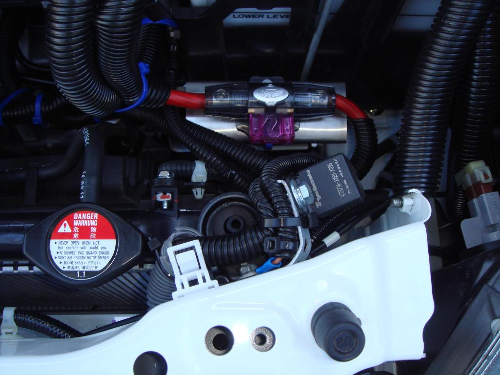
Below is the picture of the Fuse Block.
The Right side of the fuse block only have 1 wire, that is the INPUT Wire from Alternator Positive Output.
The Left Side of the fuse block have 2 wire, one is the big 3 wiring direct connect to Positive Battery Terminal, The other wire is the Factory Main Positive Wire that USED TO connect to the alternator output.
Notice I had a STAINLESS STEEL Mounting Plate bought from Home Depot,
and modified (drilled) a bit so it will fit all the bolt holes.
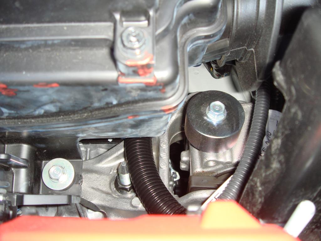
I mount it to the engine block using the Intake Manifold Bolt.
I also used the same Mounting Plate for mounting my other Fuse Block for my Powered Subwoofer, and I place this other fuse block near the battery.
Here is the Home Depot Product that I used: Prime-Line Stainless Steel Door Guard Plate-U 9589 at The Home Depot
take note that the above model might not be the exact one that I buy because at Home Depot they have several size of the product above,
I forget which size that I buy, but it sure is the Largest one they had so it will accomodate the width of the fuse block. Take time at Home Depot when you want to buy this mounting plate.
Take note that I wrap most of the Big 3 wiring with the black plastic wire protector for extra protection. It might not reveal the pretty cable jacket of the big 3 wire cable that I had,
but it sure make it look for FACTORY STOCK.
(although that fuse block sure not look factory stock hahaha)
Notice on the Positive Battery terminal, there are 2 big wire connected,
one is from the Main Alternator Fuse Block, the other is to the Rockford Fosgate Fuseblock for my Powered Subwoofer.
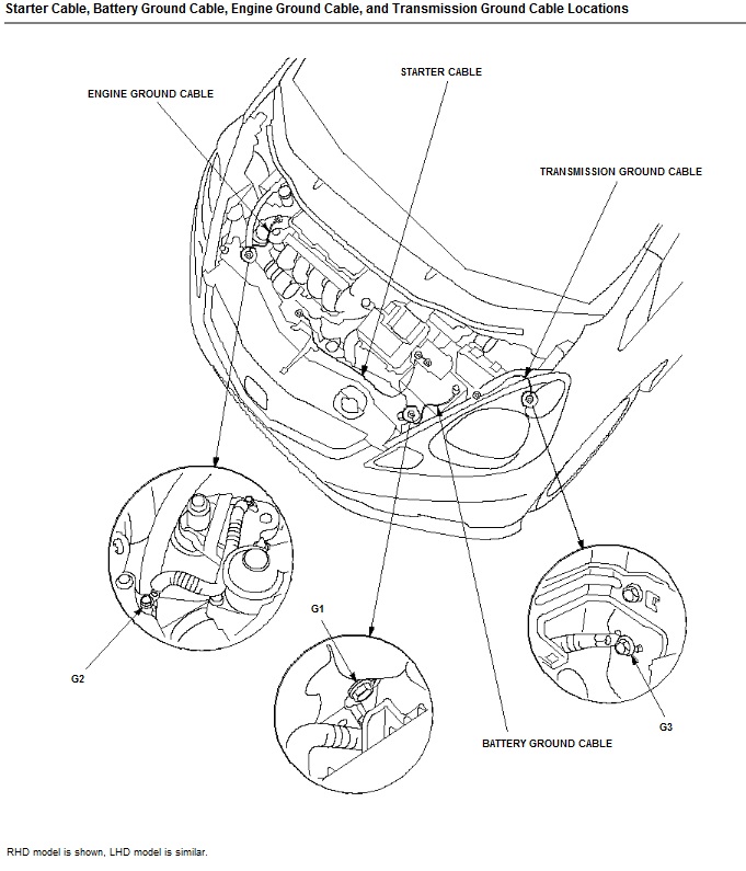
at the picture below, you will see Rockford Fosgate NEGATIVE Battery Terminal, I connect the Negative Battery Terminal to SEVERAL ORIGINAL Grounding on the car.
One behind the Head Light, one behind the battery. (this is all Driver Side)
This is where the other grounding point on the driver side behind the battery.
This one below, is on the Passenger side, I run another Grounding from the Chassis to the Engine Mounting/Block.
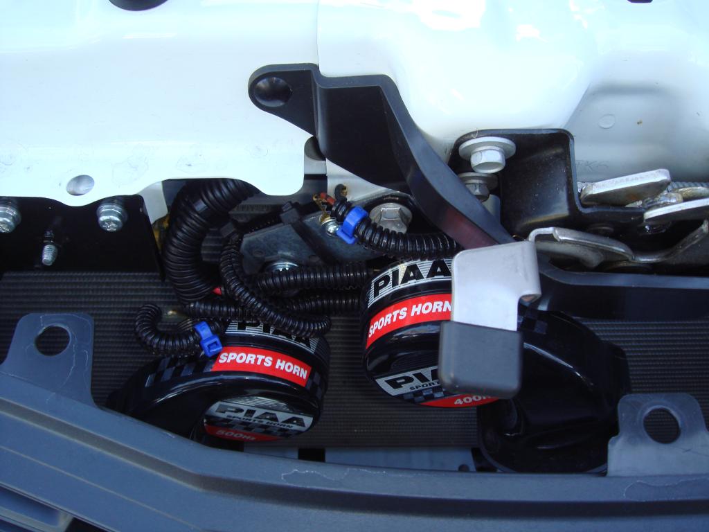
Now, this is the picture of the RELAY for my PIAA Horn and the picture further below is the picture of the PIAA Horn mounted.
Close Up Picture of the Rockford Fosgate Fuse Block for Powered Subwoofer mounted on the same Mounting Plate from Home Depot.
on the main fuse block (connected to alternator),
at the bottom of the square plastic fuse block housing,
I put a sheet of Sound Dampening Material (thick),
to further insulate it from the stainless steel plate (don't want to short the main positive wire), plus I do this to help isolate vibration from the engine.
Take note that I do NOT run the main wire from this fuse block (or from alternator) to battery near the front radiator mounting like other do, but I sneak it nearer to the engine block so further behind.
This way if my car ever have an accident (hopefully never happened),
the positive wire will not be easily hit like if I run the wire on top of the radiator mounting. so to further reduce the risk of spark from short circuit because the main positive cable were cut during the accident and expose to the chassis. Well of course if the accident is big enough,
it will still going to hit that wire cable, and this is where the fuse will help,
plus hopefully the alternator would stop spinning anyway if this ever happened,
so no spark of fire caused by short circuit.
This is the picture that show how I run the wire behind the radiator fan and not on top of the radiator housing:
I got this idea when I see several of the factory wiring also run behind the intake manifold covered with hard plastic, and I run my big 3 wiring following that route to, plus I cover it with plastic protector
to further protect from engine block heat.
Last edited by BMW ALPINA; 03-14-2013 at 03:19 PM.
man i'm looking to do this myself, but u sure don't like to keep it simple. all i see is black wire protectors everywhere. makes me dizzy trying to follow. good job nonetheless. i think i will go with a simpler cleaner install. already ordered my parts from crutchfield/sonic.
man i'm looking to do this myself, but u sure don't like to keep it simple. all i see is black wire protectors everywhere. makes me dizzy trying to follow. good job nonetheless. i think i will go with a simpler cleaner install. already ordered my parts from crutchfield/sonic.
Well, that is the point of all the black wire protectors, I want to make it look as factory stock as possible.
but trust me, when you do it yourself, you will feel the complication...
even choosing where is the ideal place for ground point is going to be confusing...
Originally Posted by AKSnowman
how do you like the PIAA horns? I was thinking about getting a set. Looks like there is wiring changes that need to happen?
I like the PIAA horns, it sound loud enough without being too loud.
also I choose the lower frequency model (they have 2 model to choose).
The wiring changes were almost none if you decide not to use Relay,
but I decide it is best to use relay so the higher current needed from the horn will not tax the factory horn wiring.
the PIAA came with decent wiring instruction, so it will be a good start
if you don't want to use relay.
if you don't use relay basically is:
there is only one wire (positive) coming to the stock factory horn,
and you split it into 2, to connect to the 2 PIAA horns positive side.
then you use the negative ground wiring that came with the PIAA horns and connect it to the body/chassis.
(the factory horn it self use it's mounting bolt as the ground point).
Also for cleaner install you can cut a U shaped male wire connector into a smaller pin size and you can insert it into the factory female connector.
the u shaped male wire connector is the same thing that came with the PIAA Ground cable.
Oh, another point is,
there are 3 grounding cable from factory.
One is from Battery negative battery terminal directly to the chassis
Second is from chassis to engine mounting (behind the battery, on driver side)
Third is from chassis to engine mounting on the passenger side.
It is best if you either augment with extra wiring or replace the wire on the 3 ground above.
In my case,
for first one, I simply replace the factory cable because I use the rockford battery terminal first hole for the larger wire and connect it to the same chassis bolt that the factory use,
The factory ground cable at this point were permanently wired to the factory original negative battery terminal,
so I can not used it together with my large grounding cable. so this one is replacing
for second one, I still leave the original factory cable connected but I run another
large wire directly from the rockford negative battery terminal second hole to the same engine mounting bolt that the second factory ground wire attached too. so this one is Augment.
for the third one, I still leave the original factory cable connected but I run another wire directly from the same engine mounting bolt to the chassis bolt that hold the radiator. so this one is Augment
so by doing this, I replace/augment the entire grounding cable from factory,
and I still have some extra large cable left...
Last edited by BMW ALPINA; 05-24-2013 at 01:29 PM.
Yes, That Diagram that you had give the exact location of the 3 ground cable.
Oh, just one more thing,
when you connect/bolt the wire terminal to the chassis/body, don't forget to use sandpaper to wipe the paint from the surface of the chassis and allow larger contact area between the wire terminal and the chassis.
In stock configuration, the only true/direct unpainted contact terminal were between the thread of the bolt and the thread on the chassis.
but of course you might sand a little bit larger than required for the full contact of the terminal,
so what I did was, after I bolt the wire terminal back to the chassis, I use Honda original Touch up point to repaint the area that I had sanded but outside the contact area.
this way, the risk of rust developing around the contact area because the paint got sanded will be minimized.
I barely reach the first 35 miles of the 400 miles round trip with family today when the battery charging warning light lit up on my dashboard...
I already suspect something is not right with my crimp terminal from alternator to the first streetwires terminal block because I notice the wire loom was a bit melted when I install Sprintex... so I pull to the side of the mountain road, and I touch the terminal it is very hot... I look at my scangauge, the voltage is around 11.5 to 11.8 volts...
I turn off the engine to let everything cool, start the car again, and the warning light goes away...
I decided to turn around and travel back to my home... We are Lucky we made back because about with 15 miles away from home the warning light turn on again...
when I arrive at home I take apart the terminal and I see even the solder melted...
So I cut about 1 inch of the wire, turn out the wire still looks dark due to the melted plastic jacket now coating the wire strand... so I cut further until I reach clean wire and use a new Streetwires screw in terminal and now it should be ok...
but I am going to order a brand new 1/0gauge wire, this time I will buy a real Cooper Wire instead of a Cooper Coated Aluminum (CCA) wire that I current used...
I think this CCA wires do not transfer current efficiently and get hot easily...
hopefully everything hold up until the new cooper wire arrives...
the connection must have been loose. i had a similar issue where the battery grounds to the chassis. it was hot and i saw it had melted probably from where it was arcing. i saw a few loose wires hanging off that may have caused the arcing. i cut it like you and made sure i covered the wire ends with electrical tape to prevent any arcing. so far so good.
the connection must have been loose. i had a similar issue where the battery grounds to the chassis. it was hot and i saw it had melted probably from where it was arcing. i saw a few loose wires hanging off that may have caused the arcing. i cut it like you and made sure i covered the wire ends with electrical tape to prevent any arcing. so far so good.
Hi Ryu,
I purchase some wiring kits and ring terminal that should prevent loose connection from happening again, I should have bought this quality wire and connection instead of the cheap big 3 wiring kit with CCA wires that I had now... I am so lucky that my car not stranded on the middle of nowhere on hot summer with my family in it...
anyway here is what I bought:
Rockford Fosgate Wiring Kit and Distribution Block to fix my Big 3 Wiring kit once and for all from the current CCA (Cooper Coated Aluminum) wiring that prone to overheat to Pure Oxygen Free Cooper 0/1AWG wiring.
http://www.ebay.com/itm/291822902932?_trksid=p2057872.m2749.l2649&ssPageName=STRK%3AMEBIDX%3AIThttp://www.ebay.com/itm/301956110481?_trksid=p2057872.m2749.l2649&ssPageName=STRK%3AMEBIDX%3AIT
Monster Cable Ring Terminals (this one is discontinued and I found Amazon had the last 3 pair of new old stock so I buy all 3 pairs so I am set for the next few decades )
The advantage of this one is because it have an extended head design that will fit the small space at Alternator output bolt unlike other Ring Terminal design. https://www.amazon.com/gp/product/B0...?ie=UTF8&psc=1
Monster 300 Crimpless Ring Terminals Power 1/0 & 2 AWG Ring Term (MPC P300 CPRT 1)
Also bought several Streetwires Inter-Lok ring terminals for other 1/0AWG Big 3 wiring connection needed.
http://www.ebay.com/itm/291543882702?_trksid=p2057872.m2749.l2649&ssPageName=STRK%3AMEBIDX%3AIT
and last some extra conventional crimped ring just in case I need it:
http://www.ebay.com/itm/262456659129?_trksid=p2057872.m2749.l2649&ssPageName=STRK%3AMEBIDX%3AIT
Finally, after 3 straight days, I finished upgrading my Big 3 Wiring from the old CCA Cooper Coated Aluminum wiring to the OFC (Oxygen Free Copper) Rockford Fosgate wiring 1/0AWG. The Rockford Fosgate actually have less strain of cooper wire so it was easier to install into the terminals, but it flow electricity much better than the old CCA wiring. My volt meters was showing around 13.5 to 13.6 volts at idle, now it show between 14.0 to 14.2 volts at idle ! What an improvement !!!
Here are the pictures:
First I need to built the wires from the alternator output terminal to the first distribution block terminal,
the alternator output terminal is design that it can only fit small diameter ring terminal and this Monster 300 series ring terminal is the only high quality terminal out there that I find fit our alternator output terminal.
comparison between pure OFC on the left with the CCA on the right...
in this case, bigger do not mean better
that thick wire of CCA was so hard to insert into the ring terminal...
it is actually a disadvantage in term of contact point...
I solder the wire for the wire that goes to alternator output terminal so the ring terminal will grip better:
oh by the way, this is how I cut the wires
I make aluminum extension plate to hold another Rockford Fosgate 1 to 2 1/0AWG distribution block.
1 wire will goes to battery,
the other wire will goes to another fuse block that will feed the future audio system
Distribution blocks and circuit better ready
Here the 2 wires that goes to the battery and fuse distribution block for future audio connected:
Full of Rockford Fosgate Sexyness
Connect the wire from alternator to the Streetwires Fuse Block:
Now times for the rest of the ground wiring:
Driver side Ground terminal, that connect 2 point of car body to engine block/transmission housing:
Passenger side ground terminal, also 2 point from car body to single point on engine block/transmission:
I already have a Rockford Fosgate Battery Terminal for the Negative Post,
and since I have an extra new one, I decide to replace it, since the old is not as tight in gripping the post anymore:
Another problem, I found out the Streetwires Distribution block lower plate (plastic) is all cracked... must be because it can't stand the heat that the stainless steel plate transfer from the supercharger plus it sit right on the way of the radiator air flow...
I had ordered a Rockford Fosgate Distribution Block plus Stinger Marine Grade Circuit Breaker to replace the Streetwires... too bad since I love the look of the Streetwires Distribution Block, but Streetwires discontinued this model... (1 AWG model)...
I also going to put some MLV below the new distribution block/circuit breaker to dampened the heat transferred from the stainless steel bracket...
hopefully this will prevent plastic plate cracking in the future...
Update, I just check the MLV temperature range and it can withstand up to 225 degree F,... so it should work well...( hopefully)
Last edited by BMW ALPINA; 09-25-2016 at 08:14 PM.
Last week,
I replace the Streetwires distribution block that was having problem with crack due to heat,
and install Stinger circuit breaker instead,
I also put double MLV layer behind each circuit breaker/distribution block
to block the heat from the engine that hit the stainless steel bracket...
this Stinger circuit breaker also function to protect the factory line from altenator to the batter,
the secondary 1/0AWG line were always protected by the Rockford Circuit breaker... so now all line is full protected by circuit breaker:
 03-14-2013, 02:58 PM


 )
)