When you click on links to various merchants on this site and make a purchase, this can result in this site earning a commission. Affiliate programs and affiliations include, but are not limited to, the eBay Partner Network.
I just finished up the installation of a NVX / JBL audio system in my 2016 Fit. The subwoofer enclosure took a day to build, and installing the speakers and electronics took two full days, from 7 am to 11 pm, stopping for meals. The install is about 95% complete, with some cosmetic details remaining. I relied heavily on previous install threads, but did some unique things that are worth sharing with the group. So, here we go...
System summary:
120 amp breaker under the hood by the battery. 6 AWG copper welding cable carrying power to a 500W JBL amp, driving an NVX 12 inch diameter subwoofer in a 1.25 cu-ft sealed enclosure. Installed four new 6.5 inch NVX speakers in the doors. Coaxials in the rear, and a component set up front. In the front, the tweeters from the component set are installed in the dash. The crossovers as well as the NVX 200W, 4 channel amp (50W/channel) are mounted under the dash, above the glove compartment.
First, the equipment list:
The audio components were purchased from SonicElectronix.
subwoofer / amp combo
front door speakers
rear door speakers
door speaker amp
4 gauge power cable
Radio harnesses and door speaker harnesses as specified in previous threads
10 gauge cable, power cable lugs and main breaker were surplus parts from Triple Helix
To start off, two tools in particular were invaluable during this install.
The first was my home made panel pry tool. When it came time to pry off the door panels, I found this impossible to do without a pry tool. Not having a set of plastic pry tools, and not wanting to wait to get a set, I made one from 1/8" thick lexan.
The second is a high quality set of flush cutters. For cutting wire ties off flush with no sharp edges, and in particular for modifying the stock speakers into mounting rings. I use an industrial quality cutter designed for cutting molded plastic parts off of sprues, during manufacturing. I can't recommend this tool highly enough.
To start off the build, I made a sealed subwoofer enclosure from 3/4" mdf. (Previously posted in another thread, but included here for completeness.) It has an internal volume of just over the manufacturer recommended 1.25 cu-ft. The top of the box is a panel that sits where a cargo cover would normally go. The internal height of the box is 1" taller than the depth of the subwoofer. This allows me to preserve as much cargo space below the enclosure as possible. Currently, the box needs the addition of some handles, cosmetic wrapping, and a grille of some kind to protect the speaker. The enclosure is assembled with square drive wood screws, and is sealed with caulking. The subwoofer is sealed by a rubber gasket which is packaged with the speaker. For future access to the interior, the speaker screws can be removed and the speaker dismounted.
Here is the pile of unopened component boxes and other supplies.
I used a short length of 10 gauge wire to connect the dual 4 ohm speaker coils in parallel. This gives a 2 ohm load to the amplifier. If you do this, be sure that your chosen amp is designed to handle your speaker wired this way. My amp is sold as a combo with this speaker, and is designed to work like this.
Also shown is a supply pigtail with Anderson Powerpole connectors previously installed by the Triple Helix electrical subteam. The terminals on the speaker could handle a single strand of 10 gauge wire, but would not take two ends twisted together. So, on the set of terminals that need two cables, I had to cut away about 1/3 of the cable strands. With the diameters reduced, the doubled cable ends would fit into the spring terminals.
I installed the subwoofer in the box. The pigtail cable needed to be run through a hole in the side, first. I made sure there was enough slack in the cable so the subwoofer could be removed if necessary.
Finally, I sealed the cable penetration with caulking and let it cure overnight.
The subwoofer is removable so the seats can be folded down. The subwoofer cable breaks at a connector near the top of the left rear seat. I mounted this connector to the plastic housing that covers the seat latch. To do this, I made a cable clamp from 1/8" lexan. One part holds the cable to the outside of the housing. The other has a tapped hole, and acts as a nut on the inside of the cover.
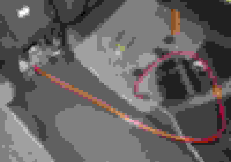
Here is the subwoofer cable snaked behind the carpet on the back of the seat. This routing allowed for passage of the cable without cutting holes in the fabric.
Here are the parts for mounting the cable to the cover.
The inside of the cover, showing the "nut" side of the installed cable clamp, and the notch necessary to pass the cable outside the cover.
The latch cover reinstalled, with the speaker wire connectors mated.
Notice the child seat attachment mount, just behind the enclosure. If the weight of the subwoofer and enclosure proves to be too much for the cargo cover shelf brackets, I'll add some structure to the box to transfer weight to the child seat mounts.
Next task was to mount the main breaker under the hood and get power to the subwoofer amp. I started by making a mounting plate for the breaker from 1/4" lexan.
The breaker is attached to the plate with flat head screws tapped into the breaker mount holes. Then I applied double stick mounting tape.
The breaker was stuck down to the top of the fuse box, under the hood.
A note about the lugs crimped to the power cable. The cable is 4 gauge. The lugs are for 6 gauge cable. I used these because they were available as surplus from my robotics team. To make them work, I drilled out the hole with a C sized drill bit, then used a countersink tool to put a chamfer on the hole to help funnel in the wires. I used the smallest sized hole I could, and since the holes were a bit oversized for 6 gauge cable, drilling them out didn't remove much material. It was tricky getting the fine stranded 4 gauge welding cable into the close fitting holes, though.
I borrowed the Harbor Freight hydraulic crimper the robotics team uses to crimp power lugs. Since the lugs are 6 gauge lugs, I used the 6 gauge dies to make the crimps. Heat shrink on the crimped portion finishes the crimping job.
I ran a short piece of cable between the positive terminal of the battery to the breaker. I had to trim off a bit of the end of the lug so it would fit under the head of the screw. In this position, the lug exists the cover that protects the positive battery terminal without modification to the cover.
I crimped a lug onto one end of the long power cable, attached it to the other breaker terminal, and routed it across the firewall.
The cable passes through a boot in the firewall which carried a large bundle of wires. Getting the power cable through the boot was one of the toughest parts of the install. There are a couple tricks that helped, once I figured them out. Using my nippers, I trimmed back the exposed ends of the copper conductors so they were below the insulation. If they stick out, the copper ends get snagged on the boot. I also used dishwashing detergent to lube up the jacket of the power cable. This made a HUGE difference .
The inner side of the boot is reachable when the glovebox is removed. The power cable is routed to the bar to which the glovebox attaches. I knew that I wanted the 4 channel amp to be mounted in the dashboard. Near the center of the bar, I tapped into the 4 gauge cable with a 10 gauge cable to supply power for the 4 channel amp. To do this I stripped off a section of insulation, separated the strands of the 4 gauge cable in half, inserted the stripped end of the 10 gauge cable through the gap, split the strands of the 10 gauge cable end, wrapping around each side of the T-connection. The splice was then wrapped with electrical tape.
The 4 gauge power cable runs across the bar and drops down at the center console.
I removed the seat bolts so I could access the entire side of the center console. I laid the cable along the lower edge.
While I was at it, I ran a couple speaker wires with the power cable from the rear of the center console, up to the dash. These wires carry the signal from the head unit to the subwoofer amplifier. All of these three wires were tucked under the edge of the center console shroud, to exit at the rear of the center console.
The red wire on the left of the previous photo is the ground wire for the subwoofer amp. The lug on this wire is attached to the aft bolt on the clamp that holds the parking brake cables. Getting this bolt out without removing the center console was a trick. Break it free with an open end wrench. Then use a socket with a universal joint to unscrew the bolt. Save yourself a bit of trouble and use a piece of tape between the cables, up to the carpet. If you don't, a socket that is dropped will roll under the carpet, back out of reach. Had to use a magnet on a stick to get it back.
Mousehole notches on the bottom of this rear cover allow the power and subwoofer wires to connect to the bottom of the amp. The wires from the head unit go up the back side of the console and emerge at the hinge. They plug into the top of the amp with some adapters supplied with the amp. I plan to replace these adapters with jacks which are a bit more compact.
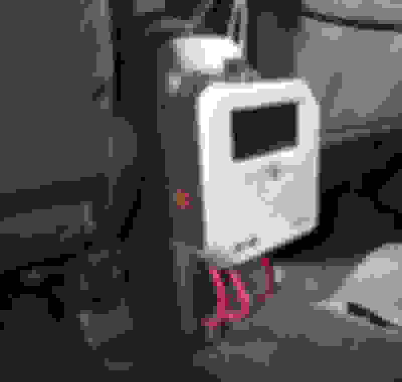
Closeup of the installed amp.
Here's the wide view with the seats up. One of the reasons for chosing this location was the big, glowey display on the unit. It seemed a shame to hide it away out of sight somewhere. Also, I rarely have passengers in the back seat, so no issues with it getting kicked by kids.
The amp is perfectly sized so the seats fold down around it, when the center headrest is removed. I never have a passenger in the center of the back seat, so this headrest will probably go into storage.
The NVX tweeters have housings for three mounting configurations: upward facing on a panel; tilted on a panel; and flat in a round hole.
I set these housings aside when I noticed that the grille on the front of the tweeter fit perfectly into the round pocket on the bottom side of the stock tweeter mounts.
I cut some notches in the plastic rim of the tweeters, and used zip ties to hold the tweeters in the housings. The housings reinstall in the dash with no indication that the tweeters have been added.
Previous threads do a great job of showing the door panel removal for door speaker replacement. I'll focus on the stuff unique to my install...
I used this same mounting technique on all four doors. Working it out on the first door took a while, but the next three went quickly. Here is the stock speaker in the door. This speaker is cast out of plastic and sits far enough from the steel for the magnet to clear the window. The door panel contacts the face of the speaker to help guide the sound out instead of having it bounce around inside the door.
I removed the speaker and used my flush cutters to cut through the posts on the back side.
Used an x-acto knife to cut through the surround.
The cone and magnet come out and can be discarded.
To remove the plastic rim around the face of the spacer, cut slots about every 1/2".
Bend the resulting tabs, and they will break off flush with the spacer face.
Remove the entire rim, and the lug as well.
Put the spacer back in the door. I used the off the shelf connector adapters to connect the speaker to the stock harness connector. Rotated the speaker so the terminals are up, and don't don't interfere with the door panel cutout. Then attached the new speaker to the door with the stock screw. The shank of the bolt is reduced diameter, and the head fits right inside the speaker rim at the slotted hole.
I used a 3/32" drill bit to drill holes in the spacer for three supplied screws in the other four slots. If you do the bottom slot first, you can let go of the speaker to do the remaining slots. Don't overtighten until all the screws are installed lightly. Then finish by evenly tightening all four screws, and reassembling the door panel.
As the previous threads show, to access the back of the radio, you need to remove the gauge cluster bezel, center vent assembly, and radio panel itself. When these are removed, it's easy to pop off the face panel just above the glove compartment, giving access to the interior of the right side of the dashboard. This helps tremendously when installing the electronics. There are two flat bars that run from the dash face to a metal tube towards the firewall. This was where I decided to mount the crossovers and 4 channel amp.
I started by cutting a piece of 1/8" lexan, sized to drop between the side flanges of the flat bar. I attached the crossovers to that mounting plate.
The crossover assembly can be slid up between the bars, to the right, and dropped on top of the RH bar. The lexan plate holds the assembly loosely on the bar.
This puts the crossovers conveniently in front of holes which can be used to access the screw terminals, if necessary.
The 4 channel amp has little feet supplied in its packaging. If these feet are attached, they can be used to zip tie the amp to the left flat bar. I measured the relative positions of the components when they were in the dash. I then laid them on the bench with the right spacing, and wired together the amp, crossovers, and harness connectors.
To install, slip the crossover assembly onto the right flat bar. Slip the amp onto the left flat bar. Then poke the harness connectors to the left, behind the radio.
Again, the connections for the amp end up conveniently located where they can be accessed through a hole.
I left enough slack in the wires so either the crossovers or the 4 channel amp could be dropped back down between the bars, for better access. I made the final connections for the power and ground to the amp, the wires that feed the subwoofer amp, and plugged in the radio harness connectors. Then the system is ready for power testing. During testing I needed to drop the crossovers to remove their covers and flip a switch to give the treble a -3 db cut. After replacing the crossovers, I dropped the amp to set the gain with the gain adjuster knobs. With the amp replaced, both components were attached to the flat bars with zip ties, and the loose wire bundles were dressed up.
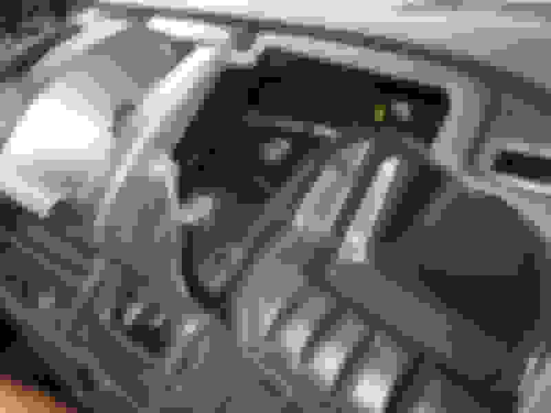
Wide view of the under dash area.
Closeup of the dressed wire bundles.
Looking left, toward back of radio.
With everything tidy, the dashboard needs reassembled. This went amazingly quickly, considering how long it took to get it apart. This car is definitely designed for quick assembly.
That's it for now. I didn't bother taking "after" pictures, as everything looks pretty much the same as when I started. It just sounds much, much better...
There is still some tidying to do and some loose ends to take care of. For example, I didn't order a second connector harness from which to steal pins for my wheel controls. I'll need to go back and install those pins when the harness arrives. I also need to wrap the ends of the firewall boot with electrical tape. Not looking forward to that job...
Only two major gotchas:
- On the rear doors, there are small, black triangular pieces in the window corners. These do NOT need to be removed to remove the door panels. In attempting to do so, I ended up breaking the mounting post on one, so I'll need to replace that part.
- It was brutally hot and humid the days I did this install. I kept myself sprayed with OFF to keep the mosquitoes at bay. Unfortunately, I must have sweated some OFF onto the glossy plastic part that surrounds the shifter. OFF is not kind to plastic. The surface has been crazed, and it's no longer glossy. I'm going to need to replace that part, too. Though I just might paint it, instead, to match my color scheme.
Impressive install! What are you using for an interface from the OEM HU to your amps?
Well, both amps will accept both high level and low level inputs. Currently I'm sending the speaker output signals from the head unit directly to both amps.
What that means is that both amps are receiving audio with the low bass filtered out. Based on this post, I believe that the head unit has a low frequency cutoff at around 50 Hz, correct? This doesn't much matter for the door speakers, as both sets have a low frequency cutoff at 70 Hz anyway. It matters more for the subwoofer, which is what would normally fill in those ultra low frequencies.
The subwoofer amp I chose is pretty sophisticated, with the ability to digitally tune the low pass filter precisely. I believe I can manipulate the cutoff frequency, filter slope, and overall gain of the sub amp to lift the extreme low end enough to get the audible frequency response fairly flat. Getting that right might require the purchase of a calibrated curve test mic.
Keeping in mind that I finished the install at 11 pm last night, I haven't yet had time to do much tuning of the sound. I have a few "knobs" I can turn:
- head unit tone controls, including high and low frequencies
- gain settings for front and rear channels on the 4 channel amp
- 0 db and -3db treble cut on the tweeter crossover
- input gain control on subwoofer amp. This is normally set by playing a test CD and adjusting the level until the display says it's at the proper level.
- subwoofer amp digital low pass filter frequency and slope settings
- subwoofer amp output gain control
All that said, there is still the question of what I am shooting for. Sometimes a dead flat frequency response just doesn't sound good. Add in the fact that if you tune things perfectly in a sealed car, then open the windows, the sound changes. There is a diminishing point of returns when tuning car audio.
Thanks for your install thread, by the way. It was most helpful, and I studied it closely before starting my install.
 06-13-2016, 10:00 AM