DIY CAI using dryer hose
#1
 03-27-2008, 01:22 AM

DIY CAI using dryer hose
Disclaimer: The following is provided as a GUIDE ONLY, and neither myself, nor FITFREAK endorse, recommend, encourage nor take any responsibility for the outcome of someone else doing the following. You follow these steps at your own risk!
OK now that the disclaimer is out of the way we can get going.
This was an old thread that a member wanted reposted so here it is.
Mission: A DIY cold air intake getting air from the front bumper.
Parts needed: One or Two PVC plastic pipe butt connector 3 3/4 inch Inside diameter. One PVC plastic pipe reducer 3 3/4 reduced to 2 3/4 inch inside diameter. One 4 inch dryer hose (or hose of your choice). Two large (4 inch) hose clamps. 4 sets of 5 minute quick drying two part epoxy glue. One 6 inch section of 1/4 inch thick one inch wide metal strapping. One 1/4 inch nut and bolt.
Tools needed: 10mm wrench, 10mm socket and ratchet, Phillips screwdriver, Pliers, Dremel tool set, or other metal cutting tools, metal files assorted. Jack and jack stand. Drill and bits.
What we will be doing in this DIY is cutting a hole in the front bumper to permanently install one PVC butt connector. Then cutting a hole in the side of the stock airbox to permanently install one pipe reducer. Connect them together with the dryer hose so outside ambient temperature air enters the bumper PVC butt connector then flows up the dryer hose into the PVC reducer then into the airbox.
Since you guys should know how to cut a hole in your bumper and slowly make the hole large enough that the butt connector fits snugly into the hole you made. The front of the connector should protrude a slight bit longer then flush with the bumper.
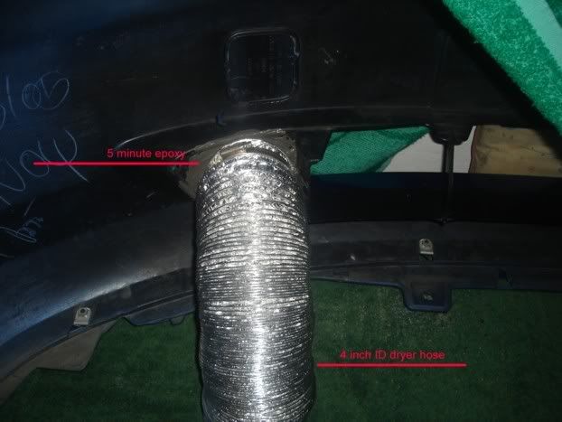
This is what it looks like from the rear (front view later). I forgot one important step... on the inside of the connector is a ridge 1/2 way up the inside to keep the two sections of pipe centered in the joint. This ridge is an airflow obstruction so cut it out with your dremel tool or other method, it takes about a minute with the dremel tool.
I found that it was easier to cut this hole while the bumper was still attached to the car because the right side in this photo is VERY tight to the frame (photos later) if you want the best position for airflow (as determined by a homemade manometer).
I got the connector snuggly installed into the new hole checked the clearance one last time and on the OUTSIDE of the hole used some duct tape to hold it in place and to prevent the epoxy from flowing out the hole. Then I stood the now removed front bumper cover assembly onto the front so the front part was now resting on the ground.
I then mixed up a batch of the 5 minute epoxy following the instructions on the tube and let it flow off the little mixer down into the space around the connector until there was a nice thick layer of wet epoxy around the whole of the pipe connector. I let this layer set for 5 minutes and put ANOTHER layer of epoxy on top of the first layer and outward onto the area of old plastic part of the bumper so there was some side support to the new pipe. Now the hard part prop up the bumper cover assembly and I let it dry OVERNIGHT. I had done this step about 9000 km ago and still no cracking or any problems.
After overnight I slipped one hose clamp over the 4 inch dryer hose and put the dryer hose over the section of connector sticking out and clamped it down.
But while I was waiting it was time to do the whole hole thing into the side of the airbox. I eyeballed the reducer while the airbox was still on the car then took it off and started making my hole.
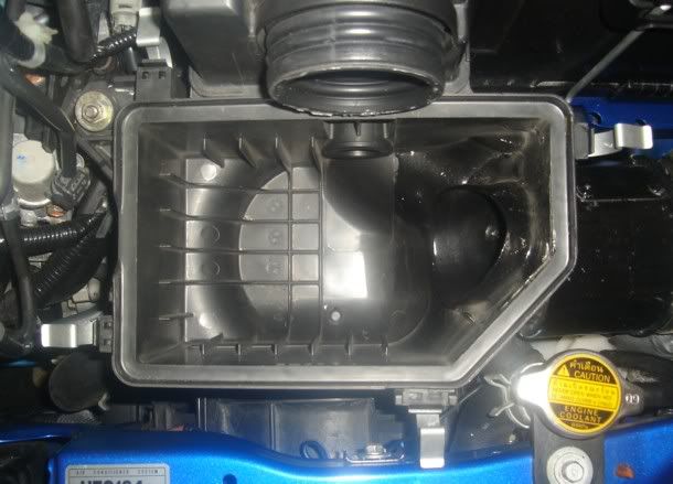
As you can see from this photo there are SEVERAL different angles and bumps and areas you have to keep checking then cut a little then check some more so you don't end up cutting too much of a hole in some of the strange angles. then once it is fitting snug I did the same duct tape on the outside and epoxy on the inside BUT this time there are so many angles you have to level for one batch of epoxy then let that dry then turn the airbox and level for another angle until there is epoxy around the whole of the reducer. I measured and checked and ended up going with the smaller reducer but you MAY be able to put in a bigger ID section if you are good at cutting and shaping.
Now that the box is dry you notice that the section of the box going outward toward the fender had a bracket with a hole in it to connect to a bracket to support the box that pipe of the stock airbox is now cut away. In the photo above if you look into the reducer you can see the head of a bolt. This bolt has a pipe of the metal strapping with a hole drilled in it and then it leads over to the stock bracket. Drill a hole into the piece of strapping that is directly over the hole in the stock bracket and use the original bolt to hold everything in place.
Now we are left with a decision for you. The pipe reducer sticks out about an inch or two and I ran like that for about 6 months and found that the cheap dryer hose I had been using kept wearing out close to the reducer so I extended the length of the reducer by super gluing ANOTHER straight section of BUTT connector to the original reducer so there was another 4 inches of plastic extending out the side of the airbox and that stopped the dryer hose from failing in that area.
Just so everybody understands you CAN use the 3 1/2" hose without cutting the fender area the hose just has to be wiggled and pushed carefully into the stock hole.
If you do not mind a few spots in the dryer hose that get squashed down to about 2-3 inches just slip the bumper assembly back on and run the dryer hose into the engine bay from the inside the fender area clamp it and you are done. I ran like this for a year but on my last trip to the States I found a 4 inch dryer hose And in the next section I will be replacing the 3 1/2 inch dryer hose with the new 4 inch and cutting out some more room so the hose doesn't get squashed.
Now we are going to get down to the business of cutting a nice big hole for the new 4 inch hose to go through.
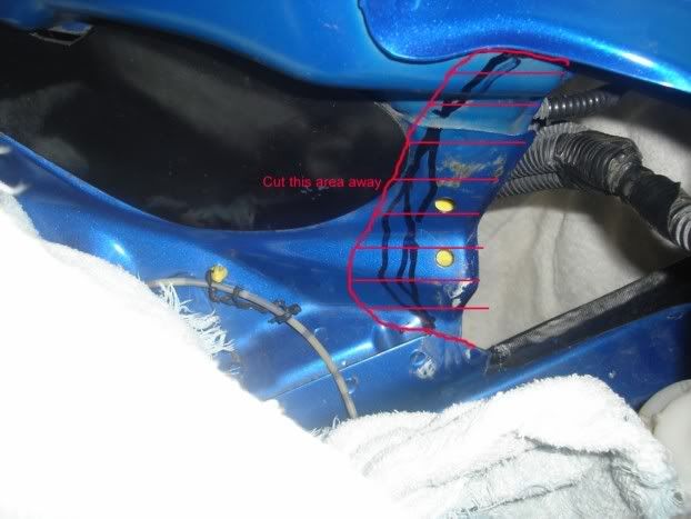
Since I used to work in a body shop I have no fear about cutting metal on my body but if you have any doubts skip these steps and go with a 3 1/2 inch hose. But if you have NO FEAR hold up the new hose and make some lines to mark out what you need to cut away so the new hose fits. The above photo is in the engine bay looking out.
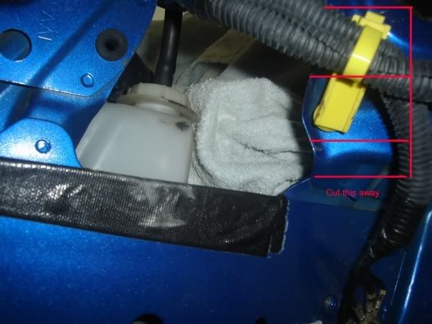
After you have jacked up the car to take the front bumper off and installed your jack stands go ahead and remove the complete plastic fender liner and of course your wheel and tire so you have some working room under the fender. This is the view from inside the wheel well.
Now the "FUN" part use your dremel tool or what ever metal cutting tools you are familiar with and cut those sections away. I found it easier to cut from the engine bay for some sections then under the fender to get at other sections. Just the cutting took me about 1/2 an hour with the dremel tool using a heavy duty cut off wheel.
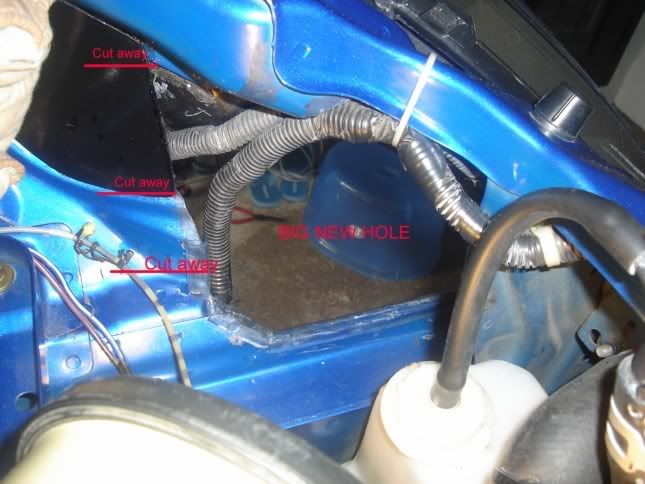
Like the photo said BIG NEW HOLE looking out from the engine bay. In the top part of the photo you can see a white looking wire tie that I had holding the stock headlight wire loom out of the way of the BIG NEW HOLE.
If you look closely you can see I used my cheapo non-matching touch up paint to coat the raw metal edges to prevent any rust from forming on the freshly cut metal edges. The big black part showing in the hole with a white J on it is the bottom of the headlight unit. The black oval looking part at the left edge of the new hole is a plastic cover I had made to close a large hole on the fender before this mod you may not have it on USDM models.
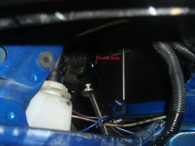
This is the big new hole looking in from the fender well. Look at the nice clear shot to the TB. You can also see the stock bracket that holds up the outer end of the airbox with a silver bolt sticking out of it.
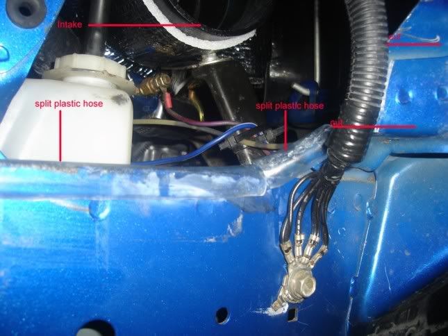
Now the airbox is back in place and you can see the silver insulation that I had added. The strapping you made can be seen leading to the stock bracket holding up the right end of the airbox.
I split some clear plastic hose lengthwise and slid it onto any sharp edged metal so the dryer hose won't get cut or chaffed.
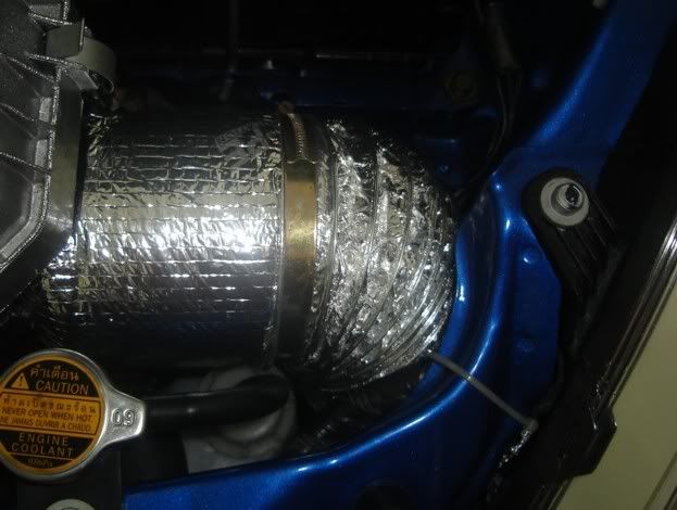
All done but the cleaning up and picking up all the tools scattered around. You can see better the new insulation that I used. Normally I just do the bottom half but on this part it looked bad so I did the whole thing for some blingness. That folks is a new new 4 INCH going into the fender with no kinks or sharp bends.
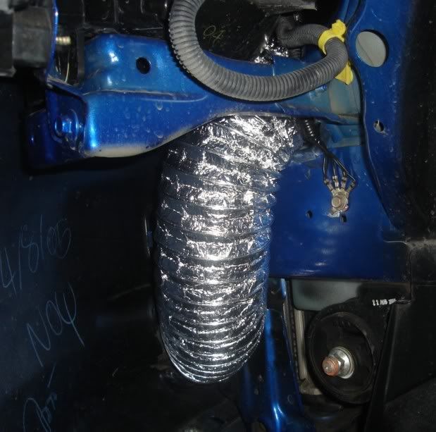
There it is about 2 feet of 4 inch dryer hose going straight up into the engine bay with no obstructions. The vertical angle of the hose keeps me from worrying about hydro lock too much because I don't think the engine has the vacuum to pull 4 inch's of water straight up a foot. But if the water is that deep I will have more to worry about besides hydro lock. you can see how close the FIT is between the hose and radiator support it's tight.
(NOTE: this photo was taken before the 98 cent bowl lid bellmouth DIY was installed)
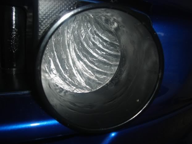
From the front if you look REAL close you can see the new hole around the connector with the epoxy touched up with black paint. If you look 1/2 way down the hole you can see the smoothed off grind marks where the ridge was ground off. And yes I do have a screen for the hole made from a bathroom soap holder but it's out for the photo.
You can't see it in the photos but I have used the same insulation that I used for my intake manifold and put it with glue around the bottom half of the airbox and it works wonders in keeping the airbox temps down to outside air temps.
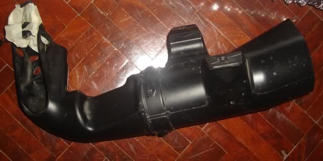
Here is a photo of the stock air intake going from the fender to the stock airbox.....
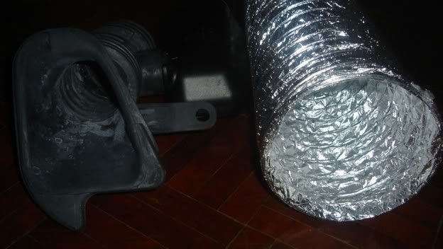
That shows just how much MORE AIR that you can move compared to stock.
Here is the stock piping inside the fender TINY...
So there it is my DIY cold air intake.
EDIT: I can't leave well enough alone so I had to make a replacement PVC pipe inside the fender to replace the dryer hose. sorry there is only one photo but really all you are doing is making a stack of PVC parts to replace the hose. No real big problem reason to make this mod other than it is more resistant to wearing out.
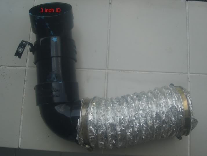
All you need is one 90 degree bend a piece of straight 3" PVC pipe and a 45 degree bend. Just pull the inner fender lining and then it's just a matter of holding things in place with no glue and cutting and fitting until it FITS. you need a short section of hose to connect the two PVC sections and in the photo the pipe is the section that connects to the intake in the grille. You need another piece to connect to the air box. you can also see the small bracket I made from some universal bracket material you can get at any hardware store. There is a threaded hole under the fender that this bracket can be bolted to.
So now you have to decide where you are going to put the intake if you love your foggies, if you want to modify your fender and if you want to modify your airbox. Then just DO IT!!!!
OK now that the disclaimer is out of the way we can get going.
This was an old thread that a member wanted reposted so here it is.
Mission: A DIY cold air intake getting air from the front bumper.
Parts needed: One or Two PVC plastic pipe butt connector 3 3/4 inch Inside diameter. One PVC plastic pipe reducer 3 3/4 reduced to 2 3/4 inch inside diameter. One 4 inch dryer hose (or hose of your choice). Two large (4 inch) hose clamps. 4 sets of 5 minute quick drying two part epoxy glue. One 6 inch section of 1/4 inch thick one inch wide metal strapping. One 1/4 inch nut and bolt.
Tools needed: 10mm wrench, 10mm socket and ratchet, Phillips screwdriver, Pliers, Dremel tool set, or other metal cutting tools, metal files assorted. Jack and jack stand. Drill and bits.
What we will be doing in this DIY is cutting a hole in the front bumper to permanently install one PVC butt connector. Then cutting a hole in the side of the stock airbox to permanently install one pipe reducer. Connect them together with the dryer hose so outside ambient temperature air enters the bumper PVC butt connector then flows up the dryer hose into the PVC reducer then into the airbox.
Since you guys should know how to cut a hole in your bumper and slowly make the hole large enough that the butt connector fits snugly into the hole you made. The front of the connector should protrude a slight bit longer then flush with the bumper.
This is what it looks like from the rear (front view later). I forgot one important step... on the inside of the connector is a ridge 1/2 way up the inside to keep the two sections of pipe centered in the joint. This ridge is an airflow obstruction so cut it out with your dremel tool or other method, it takes about a minute with the dremel tool.
I found that it was easier to cut this hole while the bumper was still attached to the car because the right side in this photo is VERY tight to the frame (photos later) if you want the best position for airflow (as determined by a homemade manometer).
I got the connector snuggly installed into the new hole checked the clearance one last time and on the OUTSIDE of the hole used some duct tape to hold it in place and to prevent the epoxy from flowing out the hole. Then I stood the now removed front bumper cover assembly onto the front so the front part was now resting on the ground.
I then mixed up a batch of the 5 minute epoxy following the instructions on the tube and let it flow off the little mixer down into the space around the connector until there was a nice thick layer of wet epoxy around the whole of the pipe connector. I let this layer set for 5 minutes and put ANOTHER layer of epoxy on top of the first layer and outward onto the area of old plastic part of the bumper so there was some side support to the new pipe. Now the hard part prop up the bumper cover assembly and I let it dry OVERNIGHT. I had done this step about 9000 km ago and still no cracking or any problems.
After overnight I slipped one hose clamp over the 4 inch dryer hose and put the dryer hose over the section of connector sticking out and clamped it down.
But while I was waiting it was time to do the whole hole thing into the side of the airbox. I eyeballed the reducer while the airbox was still on the car then took it off and started making my hole.
As you can see from this photo there are SEVERAL different angles and bumps and areas you have to keep checking then cut a little then check some more so you don't end up cutting too much of a hole in some of the strange angles. then once it is fitting snug I did the same duct tape on the outside and epoxy on the inside BUT this time there are so many angles you have to level for one batch of epoxy then let that dry then turn the airbox and level for another angle until there is epoxy around the whole of the reducer. I measured and checked and ended up going with the smaller reducer but you MAY be able to put in a bigger ID section if you are good at cutting and shaping.
Now that the box is dry you notice that the section of the box going outward toward the fender had a bracket with a hole in it to connect to a bracket to support the box that pipe of the stock airbox is now cut away. In the photo above if you look into the reducer you can see the head of a bolt. This bolt has a pipe of the metal strapping with a hole drilled in it and then it leads over to the stock bracket. Drill a hole into the piece of strapping that is directly over the hole in the stock bracket and use the original bolt to hold everything in place.
Now we are left with a decision for you. The pipe reducer sticks out about an inch or two and I ran like that for about 6 months and found that the cheap dryer hose I had been using kept wearing out close to the reducer so I extended the length of the reducer by super gluing ANOTHER straight section of BUTT connector to the original reducer so there was another 4 inches of plastic extending out the side of the airbox and that stopped the dryer hose from failing in that area.
Just so everybody understands you CAN use the 3 1/2" hose without cutting the fender area the hose just has to be wiggled and pushed carefully into the stock hole.
If you do not mind a few spots in the dryer hose that get squashed down to about 2-3 inches just slip the bumper assembly back on and run the dryer hose into the engine bay from the inside the fender area clamp it and you are done. I ran like this for a year but on my last trip to the States I found a 4 inch dryer hose And in the next section I will be replacing the 3 1/2 inch dryer hose with the new 4 inch and cutting out some more room so the hose doesn't get squashed.
Now we are going to get down to the business of cutting a nice big hole for the new 4 inch hose to go through.
Since I used to work in a body shop I have no fear about cutting metal on my body but if you have any doubts skip these steps and go with a 3 1/2 inch hose. But if you have NO FEAR hold up the new hose and make some lines to mark out what you need to cut away so the new hose fits. The above photo is in the engine bay looking out.
After you have jacked up the car to take the front bumper off and installed your jack stands go ahead and remove the complete plastic fender liner and of course your wheel and tire so you have some working room under the fender. This is the view from inside the wheel well.
Now the "FUN" part use your dremel tool or what ever metal cutting tools you are familiar with and cut those sections away. I found it easier to cut from the engine bay for some sections then under the fender to get at other sections. Just the cutting took me about 1/2 an hour with the dremel tool using a heavy duty cut off wheel.
Like the photo said BIG NEW HOLE looking out from the engine bay. In the top part of the photo you can see a white looking wire tie that I had holding the stock headlight wire loom out of the way of the BIG NEW HOLE.
If you look closely you can see I used my cheapo non-matching touch up paint to coat the raw metal edges to prevent any rust from forming on the freshly cut metal edges. The big black part showing in the hole with a white J on it is the bottom of the headlight unit. The black oval looking part at the left edge of the new hole is a plastic cover I had made to close a large hole on the fender before this mod you may not have it on USDM models.
This is the big new hole looking in from the fender well. Look at the nice clear shot to the TB. You can also see the stock bracket that holds up the outer end of the airbox with a silver bolt sticking out of it.
Now the airbox is back in place and you can see the silver insulation that I had added. The strapping you made can be seen leading to the stock bracket holding up the right end of the airbox.
I split some clear plastic hose lengthwise and slid it onto any sharp edged metal so the dryer hose won't get cut or chaffed.
All done but the cleaning up and picking up all the tools scattered around. You can see better the new insulation that I used. Normally I just do the bottom half but on this part it looked bad so I did the whole thing for some blingness. That folks is a new new 4 INCH going into the fender with no kinks or sharp bends.
There it is about 2 feet of 4 inch dryer hose going straight up into the engine bay with no obstructions. The vertical angle of the hose keeps me from worrying about hydro lock too much because I don't think the engine has the vacuum to pull 4 inch's of water straight up a foot. But if the water is that deep I will have more to worry about besides hydro lock. you can see how close the FIT is between the hose and radiator support it's tight.
(NOTE: this photo was taken before the 98 cent bowl lid bellmouth DIY was installed)
From the front if you look REAL close you can see the new hole around the connector with the epoxy touched up with black paint. If you look 1/2 way down the hole you can see the smoothed off grind marks where the ridge was ground off. And yes I do have a screen for the hole made from a bathroom soap holder but it's out for the photo.
You can't see it in the photos but I have used the same insulation that I used for my intake manifold and put it with glue around the bottom half of the airbox and it works wonders in keeping the airbox temps down to outside air temps.
Here is a photo of the stock air intake going from the fender to the stock airbox.....
That shows just how much MORE AIR that you can move compared to stock.
Here is the stock piping inside the fender TINY...
So there it is my DIY cold air intake.
EDIT: I can't leave well enough alone so I had to make a replacement PVC pipe inside the fender to replace the dryer hose. sorry there is only one photo but really all you are doing is making a stack of PVC parts to replace the hose. No real big problem reason to make this mod other than it is more resistant to wearing out.
All you need is one 90 degree bend a piece of straight 3" PVC pipe and a 45 degree bend. Just pull the inner fender lining and then it's just a matter of holding things in place with no glue and cutting and fitting until it FITS. you need a short section of hose to connect the two PVC sections and in the photo the pipe is the section that connects to the intake in the grille. You need another piece to connect to the air box. you can also see the small bracket I made from some universal bracket material you can get at any hardware store. There is a threaded hole under the fender that this bracket can be bolted to.
So now you have to decide where you are going to put the intake if you love your foggies, if you want to modify your fender and if you want to modify your airbox. Then just DO IT!!!!
Last edited by claymore; 03-27-2008 at 01:41 AM.

Thread
Thread Starter
Forum
Replies
Last Post
bdogpot
2nd Gen GE8 Specific Fit Engine Modifications, Motor Swaps, ECU Tuning Sub-Forum
2
11-27-2012 09:31 AM
MEATBABY
2nd Generation GE8 Specific For Sale/WTB Used Parts Sub-Forum
8
03-22-2012 09:36 PM

