Wr manifold testers..
#1
 02-03-2009, 02:08 PM

Wr manifold testers..
Looking for 5 Test cars to test out the Weapon*R manifold..
Will give a discount to the takers... ( PM for Details )
New Design.. No CEL...


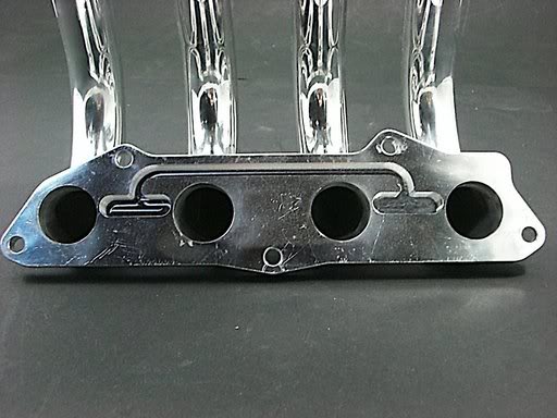
Here is the pictures of the Completed Manifold:


Will give a discount to the takers... ( PM for Details )
New Design.. No CEL...
Here is the pictures of the Completed Manifold:


#7
02-03-2009, 05:40 PM
Is this the USDM or the JDM shown here
 If this is the USDM model shown I don't understand what is happening on the back of the plate. I wouldn't mind a bit of information on how this works, my Rev2 WR manifold has the EGR port located in the center. This looks like some kind of bypass or re-routing.
Last edited by Sugarphreak; 02-03-2009 at 06:00 PM.


#14
02-04-2009, 04:11 PM
Please post lots of pics of the front and back of that lower flange, maybe some measurements as well would really be a lot of help.
#15
02-04-2009, 04:56 PM
Is this the USDM or the JDM shown here
If this is the USDM model shown I don't understand what is happening on the back of the plate. I wouldn't mind a bit of information on how this works, my Rev2 WR manifold has the EGR port located in the center. This looks like some kind of bypass or re-routing.This is the Jdm model!!!!!
#16
02-04-2009, 04:59 PM
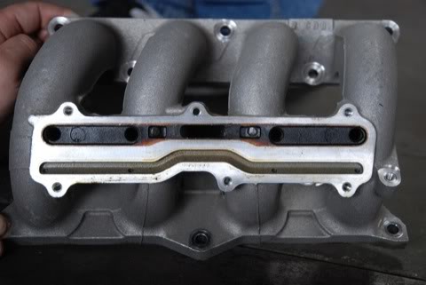
You see that large (presumably 1/2") nipple between the 2 middle runners? You have to re-route your EGR tubing there.
This is exactly how it is on mine and I still have the CEL
")
#17
02-04-2009, 05:19 PM
EGR valve reduces intake vacuum and replaces some intake airflow with EGR flow.
In this way map sensor doesn't feel anything...
Why the back of the plate is like jdm model then?
Last edited by alf74; 02-04-2009 at 05:33 PM.
#19
02-04-2009, 09:55 PM
Lemme try and explain what we did..
The reason why the ECU was seeing LOW EGR flow was because it needed to flow back into the cylinder head..
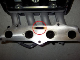
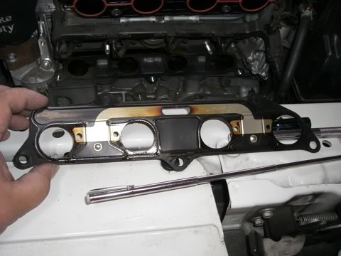
Look at the This picture of the USDM HONDA FIT.
EGR gases come from the EGR Actuator ALONG the GROOVE on the Cylinder head.
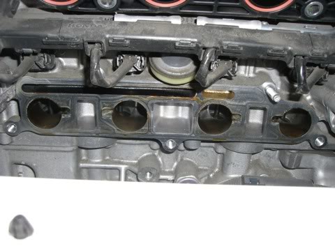
The EGR Gases flow through the BACK side of the manifold.
From the backside to the front side of the manifold, and gets re-distributed to the 4 intake ports and back into the engine..
The reason for the CEL with the old design is The EGR gases were not being distributed and the flow wasnt flowing at the rate it was supposed to be flowing at. Now if you look at the picture of the Cylinder head there are 4 wedges that allow EGR flow to flow back into the intake ports..
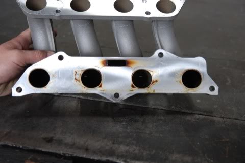
What we have done is Bypass all the flowing through the manifold etc.. etc.. ( PICTURED in pictures#1-3 ) is directly let the EGR gases flow from the EGR Actuator and evenly distribute the EGR Gases back to the intake ports..
This is basically doing the same thing that the OEM manifold was doing, which is true by looking at an OEM USDM Intake Manifold Gasket..
Flow comes from the middle and then needs to go to the 4 intake ports..
I hope i have explained it so everyone can understand what we did..
The reason why the ECU was seeing LOW EGR flow was because it needed to flow back into the cylinder head..
Look at the This picture of the USDM HONDA FIT.
EGR gases come from the EGR Actuator ALONG the GROOVE on the Cylinder head.
The EGR Gases flow through the BACK side of the manifold.
From the backside to the front side of the manifold, and gets re-distributed to the 4 intake ports and back into the engine..
The reason for the CEL with the old design is The EGR gases were not being distributed and the flow wasnt flowing at the rate it was supposed to be flowing at. Now if you look at the picture of the Cylinder head there are 4 wedges that allow EGR flow to flow back into the intake ports..
What we have done is Bypass all the flowing through the manifold etc.. etc.. ( PICTURED in pictures#1-3 ) is directly let the EGR gases flow from the EGR Actuator and evenly distribute the EGR Gases back to the intake ports..
This is basically doing the same thing that the OEM manifold was doing, which is true by looking at an OEM USDM Intake Manifold Gasket..
Flow comes from the middle and then needs to go to the 4 intake ports..
I hope i have explained it so everyone can understand what we did..
#20
02-04-2009, 10:00 PM
That is fantastic, much appreciated for the information Leo! 
Wow, there is a lot going on here that I was not aware of.
Wow, there is a lot going on here that I was not aware of.
Last edited by Sugarphreak; 02-04-2009 at 10:05 PM.