L15A running TD05H 14b + Water/Meth?
#21
 09-24-2010, 04:37 PM


All I have on my car is the bolt on hks turbo kit for the fit, it come pre-tuned to run at 5.7 lbs. of boost; you can check out the hp and torque from a dyno they have posted. Mind you this kit is tuned IMO very conservatively which to allow it to be CARB legal, this kit also utilize the stock 185 cc injectors. When compared to other turbo kits this is pretty weak I guess, but I have one and I like it.
Also when I looked at my t25 from my eclipse and the kits t25, they are orientated differently, the exhaust manifold to turbo flange is roated 90 degrees, it might be necessary to clock the turbo to allow for a better orientation, etc. Here is a pic of how the hks turbo looks like mounted to the back of the engine (pic is complements of Spooling, take from his FS thread, which I bought)

looking at the turbo imagine that it is about maybe 1-1.5 cm away from the solid break lines along the fire wall.
Maybe if the exhaust manifold was directed downwards it might provide some more room, instead of being directed back towards the firewall.
Also I believe the consensus on the forum, is that our map sensor is only good to either 10 or 11 psi.
I don't know whether using the AEM-FIC helps although that has a map sensor, i think. Comments anyone on FIC map sensor for higher boost?
Also when I looked at my t25 from my eclipse and the kits t25, they are orientated differently, the exhaust manifold to turbo flange is roated 90 degrees, it might be necessary to clock the turbo to allow for a better orientation, etc. Here is a pic of how the hks turbo looks like mounted to the back of the engine (pic is complements of Spooling, take from his FS thread, which I bought)
looking at the turbo imagine that it is about maybe 1-1.5 cm away from the solid break lines along the fire wall.
Maybe if the exhaust manifold was directed downwards it might provide some more room, instead of being directed back towards the firewall.
Also I believe the consensus on the forum, is that our map sensor is only good to either 10 or 11 psi.
I don't know whether using the AEM-FIC helps although that has a map sensor, i think. Comments anyone on FIC map sensor for higher boost?
Would a t28 fit? Are you using an internal or external wastegate? And recirculated or dumped to atmosphere?
How much boost were you running on the t25? 6-9psi? Do you know what kind of torque you are making?
My only concern is if the cams will choke the turbo. I picked up >3lbs/min from a cam change, going from factory 256* duration and .331" lift to a custom 274* and .411" lift at the same boost level and using the stock 7k redline as a control as well this was with 93 pump at ~18psi with 17* timing peak
Also to those who might be interested, I am currently relocating my battery to the trunk with 1ga. wire and installing an external shut off switch as per NHRA and Land Speed rules. Heres what that might look like:
Last edited by TunaDaMan; 09-26-2010 at 01:34 AM. Reason: to make it more aesthetically pleasing
#22
09-24-2010, 07:24 PM
Join Date: Sep 2010
Location: Chicago, Illinois
Posts: 4,424
All I have on my car is the bolt on hks turbo kit for the fit, it come pre-tuned to run at 5.7 lbs. of boost; you can check out the hp and torque from a dyno they have posted. Mind you this kit is tuned IMO very conservatively which to allow it to be CARB legal, this kit also utilize the stock 185 cc injectors. When compared to other turbo kits this is pretty weak I guess, but I have one and I like it.
Also when I looked at my t25 from my eclipse and the kits t25, they are orientated differently, the exhaust manifold to turbo flange is roated 90 degrees, it might be necessary to clock the turbo to allow for a better orientation, etc. Here is a pic of how the hks turbo looks like mounted to the back of the engine (pic is complements of Spooling, take from his FS thread, which I bought)
looking at the turbo imagine that it is about maybe 1-1.5 cm away from the solid break lines along the fire wall.
Maybe if the exhaust manifold was directed downwards it might provide some more room, instead of being directed back towards the firewall.
Also I believe the consensus on the forum, is that our map sensor is only good to either 10 or 11 psi.
I don't know whether using the AEM-FIC helps although that has a map sensor, i think. Comments anyone on FIC map sensor for higher boost?
I'd be willing to bet that if you found a T28 Compressor cover and CHRA you could swap that right in! Or have the T25 cover you have machined by a diesel shop to fit the slightly bigger comp wheel of the T28!
Did HK$ really make the manifold and turbine housing one piece, as it appears in that pic? Any chance you have a datalogger or know what your Injector Duty Cycles look like at ~5.7psi on 185cc's?
That hot side looks really big too, way bigger volute than my 14b, at least from what I can see on the outside contours. Where do you typically see full spool?
I don't think I like the idea of having my turbo boiling my brake fluid or melting my plastic dashboard though

Maybe some ceramic coating and a blanket will will help that. And AEM carries a bunch of different MAPs so I would imagine using a 3 bar (would allow for a max ~29.4psi boost over atmospheric pressure) should more than cover my needs.
Now if I could sleeve the motor, find an acceptable rotating assembly and get my meth kit in, this would allow me to safely run the max ~21psi and 34lbs/min the compressor map says is still efficient, and my own testing confirms.
After that, there is no reason (other than exploding driveline pieces
 ) that a ~2450lb 5spd Fit could not run a low 12 or high 11 second pass @ ~120mph.
Now that would be fun though a tad ambitious, considering that is deep into C6 Z06 (with a driver mod) territory.

EDIT: The more I look at this picture the more I wonder.... where the heck does the internal wastegate go to? The downpipe/oxygen sensor housing flange only shows piping from the exducer and not the bypass, where it just looks like a flat block off plate.
Last edited by DiamondStarMonsters; 09-24-2010 at 07:37 PM.
#23
09-24-2010, 09:39 PM
For the ones that I do have an answer for at the moment, yes I did move the coolant banjo bolt so that the pipe sits straight instead of at angle, Im pretty sure we can switch it with a t28 chra and compressor housing or with the chra and a modified t25 compressor housing ( I was planning to see if I could just switch it with my eclipse's chra if my turbo ever died) and no the exhaust manifold and the turbine housing are not one piece.
The turbo is internally waste gated if you notice the flat part on the back of the downpipe that is where it opens up. Not the best design in my opinion, although it does look like there is enough space for it to open because on the inside it is sorta hollowed out so that whole thickness if the flange isn't just flange
The turbo is internally waste gated if you notice the flat part on the back of the downpipe that is where it opens up. Not the best design in my opinion, although it does look like there is enough space for it to open because on the inside it is sorta hollowed out so that whole thickness if the flange isn't just flange
#24
09-25-2010, 03:33 AM
Join Date: Sep 2010
Location: Chicago, Illinois
Posts: 4,424
For the ones that I do have an answer for at the moment, yes I did move the coolant banjo bolt so that the pipe sits straight instead of at angle, Im pretty sure we can switch it with a t28 chra and compressor housing or with the chra and a modified t25 compressor housing ( I was planning to see if I could just switch it with my eclipse's chra if my turbo ever died) and no the exhaust manifold and the turbine housing are not one piece.
The turbo is internally waste gated if you notice the flat part on the back of the downpipe that is where it opens up. Not the best design in my opinion, although it does look like there is enough space for it to open because on the inside it is sorta hollowed out so that whole thickness if the flange isn't just flange
The turbo is internally waste gated if you notice the flat part on the back of the downpipe that is where it opens up. Not the best design in my opinion, although it does look like there is enough space for it to open because on the inside it is sorta hollowed out so that whole thickness if the flange isn't just flange
I think I am going to see if there are any OBD2 data loggers that work with the Fit to just get an idea of what sort of IDCs, etc. the N/As see on a daily basis.
Does anyone know who makes this chin spoiler? I've seen it on 6-7 Fits on this forum now, and they all look identical? Is it even strong enough or shaped to provide actual downforce? Cuz that would just be a bonus..
#25
09-25-2010, 04:00 AM
Join Date: Sep 2010
Location: Chicago, Illinois
Posts: 4,424
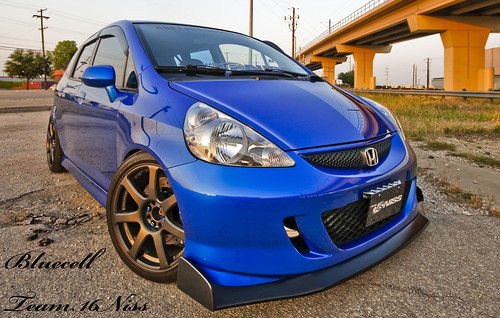
I found a thread with a guy who sells a 2 piece splitter, where are these solid 1 piece splitters like above coming from?
#26
09-25-2010, 10:26 AM
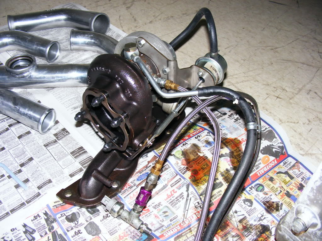
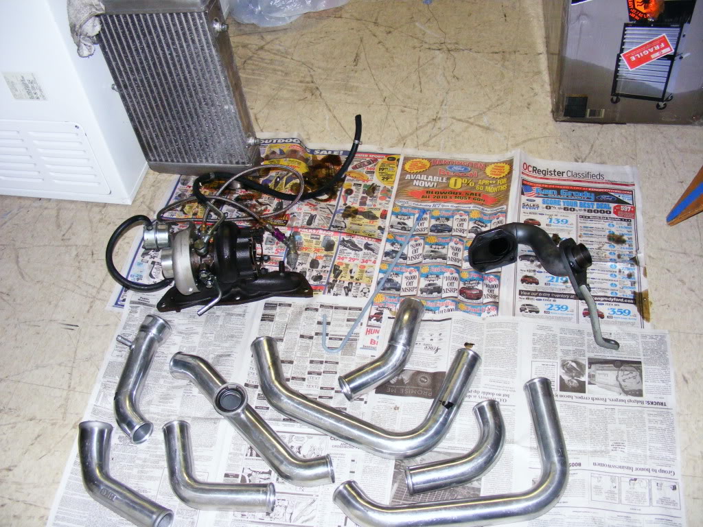
as you can see in the pictures i took while cleaning the turbo kit up after it arrived at my house, the internal wastegate does have enough room to open as provide by the space in the turbine housing and the space on the downpipe, i just thought that they could have designed it to be more like the dsm exhaust elbow
Last edited by TunaDaMan; 10-21-2010 at 03:08 PM. Reason: photo missing, now fixing links
#27
09-25-2010, 03:27 PM
Join Date: Sep 2010
Location: Chicago, Illinois
Posts: 4,424


as you can see in the pictures i took while cleaning the turbo kit up after it arrived at my house, the internal wastegate does have enough room to open as provide by the space in the turbine housing and the space on the downpipe, i just thought that they could have designed it to be more like the dsm exhaust elbow
So how long did the install take? Do you have to pull the motor to get it in? I am guessing all this comes at the sacrifice of the fog lights to fit the FMIC?
#28
09-25-2010, 03:35 PM
thats the J's Racing lip. the blue fit is a JDM converted fit and the red one is the USDM J's lip.
#29
09-25-2010, 03:41 PM
Join Date: Sep 2010
Location: Chicago, Illinois
Posts: 4,424
Jay Racing
Or is this a seperate "J's Racing" outfit?
#30
09-25-2010, 04:03 PM
Join Date: Sep 2010
Location: Chicago, Illinois
Posts: 4,424
I've decided I am going to just use a Bosch -044 inline fuel pump and -6AN braided stainless lines with a Golan SS filter and element. This way even if I found a way to fit a front mount GT35R under the hood I won't have to screw with the fuel delivery (minus injectors) ever again.
It is so much easier than screwing with a in-tank pump like a walbro GSS342, and it will handle boost better.
Shown below going clockwise.. Walbro 190lph, stock 1G dsm fuelpump and a Bosch -044

It is so much easier than screwing with a in-tank pump like a walbro GSS342, and it will handle boost better.
Shown below going clockwise.. Walbro 190lph, stock 1G dsm fuelpump and a Bosch -044

#32
09-25-2010, 04:04 PM
Thanks for the quick response! Are you referring to these guys:
Jay Racing
Or is this a seperate "J's Racing" outfit?
Jay Racing
Or is this a seperate "J's Racing" outfit?
J's Racing The X'tream Honada Ride
#33
09-25-2010, 04:05 PM
Join Date: Sep 2010
Location: Chicago, Illinois
Posts: 4,424
I already have a few intercoolers to choose from, plus another medium sized unit a friend is borrowing:

#34
09-25-2010, 04:06 PM
Join Date: Sep 2010
Location: Chicago, Illinois
Posts: 4,424
I already have a couple MAP sensors lying around, and here is the 5bar unit I was talking about earlier mounted on the UICP of one of my cars:

Last edited by DiamondStarMonsters; 09-25-2010 at 04:12 PM.
#35
09-25-2010, 04:07 PM
Join Date: Sep 2010
Location: Chicago, Illinois
Posts: 4,424
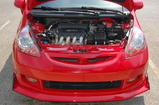
Another shot I used for scale when I was measuring the space available for a turbo and potentially a custom fab ram horn manifold:

Last edited by DiamondStarMonsters; 09-25-2010 at 04:12 PM.
#36
09-25-2010, 04:11 PM
Join Date: Sep 2010
Location: Chicago, Illinois
Posts: 4,424
And a shot of my Laser as she sits this morning after a few minor parts were installed, EGR delete, new gates racing coolant hoses all around,etc. Minus snow performance methkit because I was trimming my lines and trying to make/relocate a bigger meth tank.
I think I am going to have to add a second meth nozzle either another big nozzle in the UICP, or a small M3-sized nozzle pre-turbo for additional "wet compression" as the old WW2 pilots used to call it. You can also see that I have cooked the high temp paint off my manifold
Time for a new manifold anyways, as this ported factory 2G one is just a bit too restrictive, probably going divided T3/T4 with a larger turbine housing (.70AR or larger than the .55AR I've got) slightly too much back pressure to efficiently see the +60lbs/min this thing is rated for:
EDIT: Holy Crap that picture came out huge... sorry!
Last edited by DiamondStarMonsters; 09-25-2010 at 04:16 PM.
#37
09-25-2010, 04:46 PM
Since I got my kit used I had some missing parts; hoses, fmic mounting brackets, some hose tees, block off plate for the bov (now using the black hks ssqv) I think that pretty much sums up the missing parts list, it took me two days to install. No you don't have to take out the engine, I think You're supposed to come in from the bottom, but I got everything in through the top. To install the piping and fmic you do lose the fogs (that makes me sad) and the windshield washer bottle (which I remounted in the same area and sorta ghetto rigged a hose to allow me to connect the filler neck to it)
It probably would have taken me less time to install if I had all the parts, but I also opted to drop my oil pan to drill it for my oil return line instead of using the banjo bolt that replaces the oil drain bolt (in my case my fumimoto quick drain valve) that comes with the kit. I also ran into some helper error as I had to remove my oil pan three times. Making my own brackets for my washer bottle and fmic didn't take me too long. My only other problem was not knowing which hoses from the engine I was supposed to tee off from for the coolant and vacuum (for my also ghetto rigged 1g bov on its stock pipe, used to get me home from my friends house, and used until I got the hks one)
Can someone point out the pcv valve for me? Pics would be nice
#39
09-25-2010, 11:05 PM
Join Date: Sep 2010
Location: Chicago, Illinois
Posts: 4,424
Since I got my kit used I had some missing parts; hoses, fmic mounting brackets, some hose tees, block off plate for the bov (now using the black hks ssqv) I think that pretty much sums up the missing parts list, it took me two days to install. No you don't have to take out the engine, I think You're supposed to come in from the bottom, but I got everything in through the top. To install the piping and fmic you do lose the fogs (that makes me sad) and the windshield washer bottle (which I remounted in the same area and sorta ghetto rigged a hose to allow me to connect the filler neck to it)
It probably would have taken me less time to install if I had all the parts, but I also opted to drop my oil pan to drill it for my oil return line instead of using the banjo bolt that replaces the oil drain bolt (in my case my fumimoto quick drain valve) that comes with the kit. I also ran into some helper error as I had to remove my oil pan three times. Making my own brackets for my washer bottle and fmic didn't take me too long. My only other problem was not knowing which hoses from the engine I was supposed to tee off from for the coolant and vacuum (for my also ghetto rigged 1g bov on its stock pipe, used to get me home from my friends house, and used until I got the hks one)
Can someone point out the pcv valve for me? Pics would be nice
It probably would have taken me less time to install if I had all the parts, but I also opted to drop my oil pan to drill it for my oil return line instead of using the banjo bolt that replaces the oil drain bolt (in my case my fumimoto quick drain valve) that comes with the kit. I also ran into some helper error as I had to remove my oil pan three times. Making my own brackets for my washer bottle and fmic didn't take me too long. My only other problem was not knowing which hoses from the engine I was supposed to tee off from for the coolant and vacuum (for my also ghetto rigged 1g bov on its stock pipe, used to get me home from my friends house, and used until I got the hks one)
Can someone point out the pcv valve for me? Pics would be nice
Are there any hoses going from the valve cover to the intake manifold?
#40
09-26-2010, 01:40 AM
i'm pretty sure there is only one nipple that comes off the valve cover and that goes to the intake itself. but not sure whether anything else connects to it.
The only hoses I see coming off the Intake manifold are, 1. the break booster vacuum hose which connects to the back of the black (plastic) upper intake manifold and 2. a hose which connects to the front of the lower metal intake manifold, not too sure where that one connects too exactly.
The only hoses I see coming off the Intake manifold are, 1. the break booster vacuum hose which connects to the back of the black (plastic) upper intake manifold and 2. a hose which connects to the front of the lower metal intake manifold, not too sure where that one connects too exactly.