
DIY Grounds


Thread Starter
|
Member

Joined: Jul 2010
Posts: 208
From: Arkansas
DIY Grounds
I decided to spend some money (About 10 dollars for automotive grade wire and connectors) and added some grounds...
To start off, I bought some 10-gauge wire from Advance Auto Parts. It was an 8 foot roll.

So I wanted to add another ground from the battery to the chassis, and add a ground from the engine block to the chassis and one from the transmission to the chassis.
The smart thing to do first is unhook the negative battery cable.
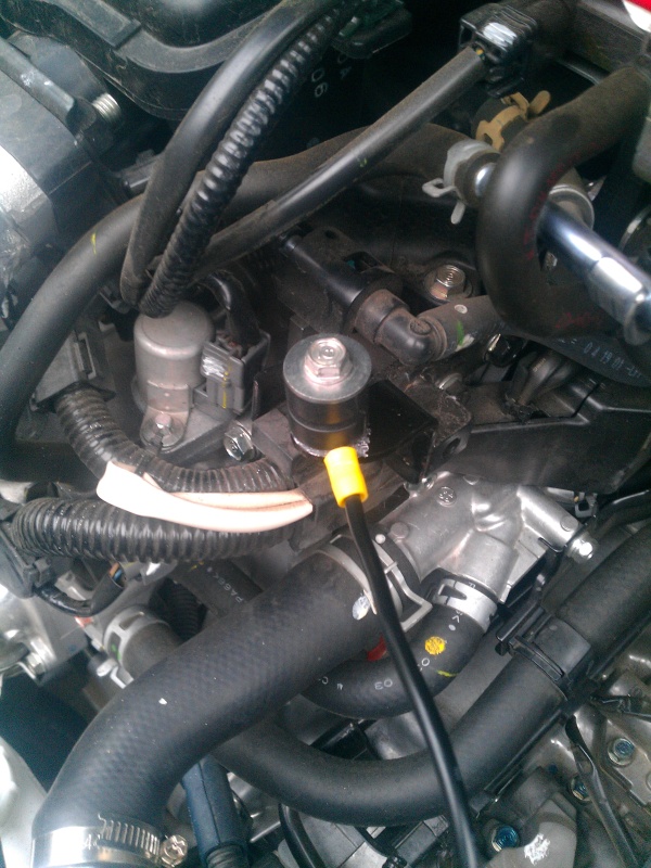
My first point I decided on was the engine block to the chassis. I used a DVOM (Fluke) and found a suitable point:
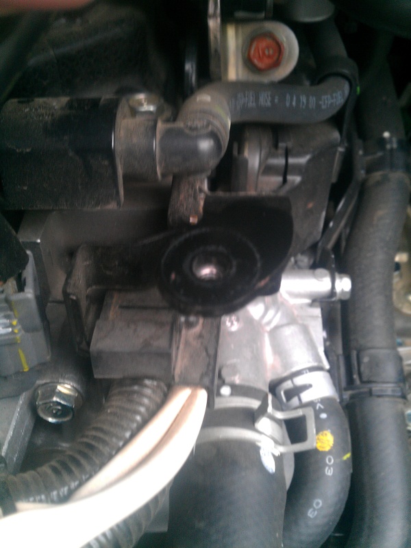 Here to...

Here. So, I whipped out a neat little tool to take off some paint.
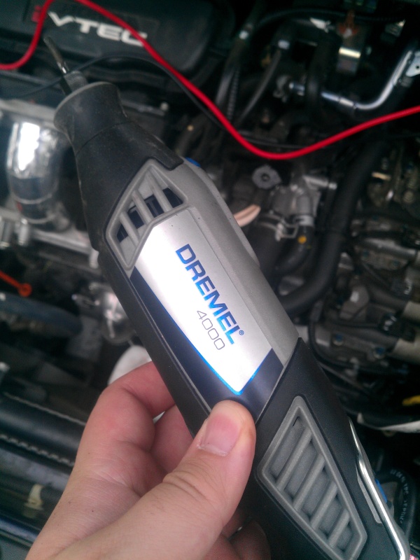
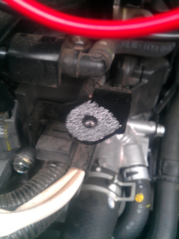
That should rough it up really good. So, using the 10 gauge wire and proper ring terminals:
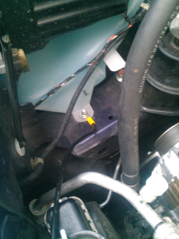
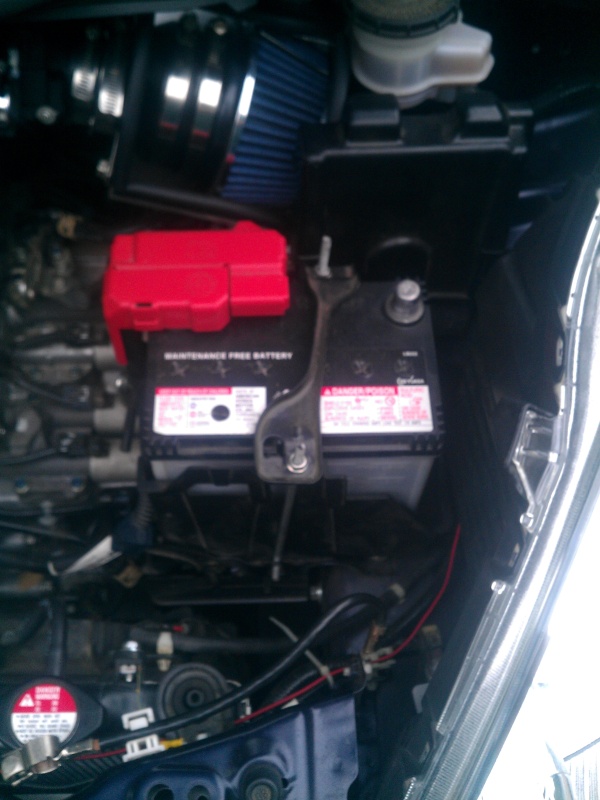
That one is taken care of, now for one from the battery to chassis. I just added a ring terminal under the 10mm nut on the battery connector. I ran a wire to a bolt on the side bracket for the ECU.
This is the bracket I'm talking about.

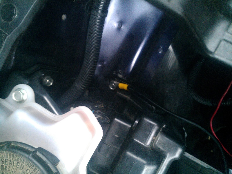
Now, I added one from another bracket that held the factory airbox that was bolted to the transmission. Same routine as before, rough up the surface with the Dremel and re-use the factory washers and bolts. I grounded it here:

So then it's a matter of making sure everything is secure and tied and free from moving parts, and to re-attach the negative battery cable. Here are the points that are now grounded:

I can't report much on any gain yet; since I had to unhook the ground cable, the ECU reset itself and is readjusting. I did take a short drive and it seemed like the starting time was quicker, but nothing absolutely outstanding. Same with throttle response: the lag did not seem quite as bad.
The only thing I did notice was the transmission seemed quicker to shift when using the paddles.
I have a Pivot Raizin in the mail hopefully, so I will probably use that to ground to the block and transmission and throttle body to a common point and then we shall see how it turns out.
To start off, I bought some 10-gauge wire from Advance Auto Parts. It was an 8 foot roll.
So I wanted to add another ground from the battery to the chassis, and add a ground from the engine block to the chassis and one from the transmission to the chassis.
The smart thing to do first is unhook the negative battery cable.
My first point I decided on was the engine block to the chassis. I used a DVOM (Fluke) and found a suitable point:
Here to...Here. So, I whipped out a neat little tool to take off some paint.
That should rough it up really good. So, using the 10 gauge wire and proper ring terminals:
That one is taken care of, now for one from the battery to chassis. I just added a ring terminal under the 10mm nut on the battery connector. I ran a wire to a bolt on the side bracket for the ECU.
This is the bracket I'm talking about.
Now, I added one from another bracket that held the factory airbox that was bolted to the transmission. Same routine as before, rough up the surface with the Dremel and re-use the factory washers and bolts. I grounded it here:
So then it's a matter of making sure everything is secure and tied and free from moving parts, and to re-attach the negative battery cable. Here are the points that are now grounded:
I can't report much on any gain yet; since I had to unhook the ground cable, the ECU reset itself and is readjusting. I did take a short drive and it seemed like the starting time was quicker, but nothing absolutely outstanding. Same with throttle response: the lag did not seem quite as bad.
The only thing I did notice was the transmission seemed quicker to shift when using the paddles.
I have a Pivot Raizin in the mail hopefully, so I will probably use that to ground to the block and transmission and throttle body to a common point and then we shall see how it turns out.

Member
Joined: Jan 2012
Posts: 169
From: Inverness

I understand the cleaning of ground point but why rough it up, I would think a good contact would be two smooth surfaces with a dielectric compound to get good contact and less corrosion in the future. What were the Fluke readings of ground before mods? and after?
Thread Starter
|
Member
Joined: Jul 2010
Posts: 208
From: Arkansas
By "rough it up" I just meant take the paint off.
I don't understand what you mean. Do you mean readings of resistance before and after? Or readings of current? Or voltage drop?
Unfortunately, it was threatening to storm and I was in a hurry so I didn't really get a chance to get a lot of readings. I used it just to determine where suitable ground points were.
Member
Joined: Jan 2012
Posts: 169
From: Inverness
Why not eliminate the frame grounding for those items you are trying to get a better ground by directly connecting to battery with the copper wire, as the biggest resistance after cleaning grounding points will be using steel as conductor? Voltage drop usually used to diagnose a problem, but you didn't say exactly what the problem was you were trying to correct.
Thread Starter
|
Member
Joined: Jul 2010
Posts: 208
From: Arkansas
Why not eliminate the frame grounding for those items you are trying to get a better ground by directly connecting to battery with the copper wire, as the biggest resistance after cleaning grounding points will be using steel as conductor? Voltage drop usually used to diagnose a problem, but you didn't say exactly what the problem was you were trying to correct.
I didn't really have a problem, just something that irritated the crap out of me: The lights would dim by a lot every time the air conditioning/radiator fans would kick on. These added grounds have significantly improved that. It's still there, but not nearly as noticeable. My RPM would have to jump to near 1000 RPM while idling with A/C on before this, but afterward, the idle stays fairly consistent regardless of whether the air conditioning is on, the fans are on, or not.
EDIT:: I totally missed what you said about resistance. It's true, steel is not as good a conductor as copper, but I DID measure from the battery negative wire to one of the ground points I added and saw 0.3 ohms or less resistance...So, the body is just as good of a conductor as a copper wire.
Last edited by kurisux92; Jul 13, 2012 at 09:26 AM.
Member
Joined: Jan 2012
Posts: 169
From: Inverness
I'm new to my Fit and haven't noticed changes in rpm but will try to see if the 2012 exhibit same fluctuations. I did notice it does the same as my other vehicles when on cruise control, rpms will increase showing downshift on slight hills where I can increase speed on downhill and reduce on climb and not have it drop down a gear. I would think with the minimal size battery, alternator does all it can to makeup power use when needed so a better or heavier wire to a larger capacity battery would do the most good. Does honda use solid copper or copper coated alloy? Last week I found a bad wire on my home satellite input on flexing, steel core broke, losing signal intermittently.
Thread Starter
|
Member
Joined: Jul 2010
Posts: 208
From: Arkansas
I believe the sensation you are talking about has to do with a locking torque converter locking/unlocking. I'm not sure what wire they use. And when a car's key switch is in the "Run" position, your battery is NOT what powers your electrical system. It is your alternator, which in turn charges your battery by running at 14-15 volts. At that point, your battery acts like a big capacitor. Changing the size of the battery would help starting, but as for the lights and such, it is more than likely the wire/alternator (In my opinion...It's been awhile since I've studied this kind of thing).
Thread Starter
|
Member
Joined: Jul 2010
Posts: 208
From: Arkansas
To explain my point better:
Let's say you have a high electrical-demanding stereo system for your car. If you use this while your car is running, obviously it would require a lot of power. A lot of people that have really powerful stereo systems with amplifiers and subwoofers and what not and keep a factory alternator complain that their batteries will always die on them. This is not because the stereo is drawing from a battery...it is because the alternator (technically generator, because it puts out direct current voltage, but it accomplishes this by rectifying alternating current, so it only moves in one direction) powers electrical parts of your engine, and uses whatever is left over to charge your battery. With no power left to charge your battery, your battery doesn't charge and will drain over time (and rather quickly if you use your stereo without idling your engine, as this is where the alternator puts out the most power.)
A similar situation occured in a local school district years ago; they bought brand new buses with diesel engines, that had one alternator. In a truck/automotive application, this would usually be fine...However, a school bus has a number of lights and other electrical equipment constantly in use. It was too common to have a dead battery in the buses. Their solution was to use two alternators...one to power the lighting and accessories, and the other to power the engine electrical.
Hope that helps you understand better.

Thread
Thread Starter
Forum
Replies
Last Post
Fallen_Rock
Fit DIY: Repair & Maintenance
15
Jul 1, 2011 05:30 PM
gd3kamiwanaB
Fit Photos & Videos
26
May 24, 2010 12:32 AM