


12v 30 amp relay, where can it go?


12v 30 amp relay, where can it go?
ugh ive been trying to install a mod, but a poor DIY doesnt mention where i can put a 30 amp 12v relay. i looked where the fuses are, but doesnt seem to go any where. looking at the relay i bought, it seems to be bigger than the those in the car. heres the pics
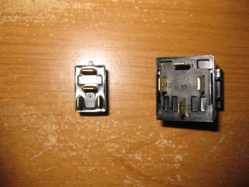
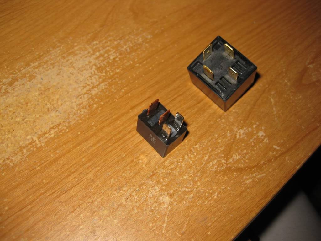
so back to question: wheres can i put a 30 amp 12v relay?
so back to question: wheres can i put a 30 amp 12v relay?
ok i think i figured it out, but i need someone to confirm before i wreck the car. I realised i didn't need to "plug in" the relay, but i can put wires to and from the relay. the thing i need to power is a single LED that is 30 mA. ive got the power source to trigger the relay on/off. and i know a way to ground it. my real problem is getting the power/power source. looking at the fuse box, theres only one 30 amp fuse. and the relay is 30 amps. this is the part im not sure about. can i put an "add-a-circuit" on that 30 amp fuse and the second slot would provide the 30 amps i need for the relay. would that work? 


You dont need 30 Ams for the relay. The relay contacts can switch 30 Amps through its contact.
The relay probably has 79 ohms resistance at 12 volts it shall draw 150Milli Amps
The led requires 30 Milli Amps your total is 180mA.
Any Fuse of 1 Amps is good
The relay probably has 79 ohms resistance at 12 volts it shall draw 150Milli Amps
The led requires 30 Milli Amps your total is 180mA.
Any Fuse of 1 Amps is good
really!? but the question remains, how do i get that power? just tap into a wire or add-a-circuit or????
i was thinking over night, and got a little confused about the grounding, and i grounding the LED to the grounding prong on the relay? or am i putting a wire from the grounding prong to lets say teh negetive of the battery? or the LED directly to the neg. battery? to ground, im thinking of tapping into the grounding wire i used for the indp. fog lights, which is a ring terminal thats screwed into the firewall. how do i go about grounding and wiring the neg./grounding(?) of the LED?
but the question remains, how do i get that power? just tap into a wire or add-a-circuit or????i was thinking over night, and got a little confused about the grounding, and i grounding the LED to the grounding prong on the relay? or am i putting a wire from the grounding prong to lets say teh negetive of the battery? or the LED directly to the neg. battery? to ground, im thinking of tapping into the grounding wire i used for the indp. fog lights, which is a ring terminal thats screwed into the firewall. how do i go about grounding and wiring the neg./grounding(?) of the LED?


Alright I'll take a shot at this...
1st: I'm guessing this mod is for a vtec light considering I don't think I've seen anyone else here use a relay to drive a single led.
2. LED's are polarity sensitive:

So with this information, take the cathode (negative side), solder a wire to it, and put a ring on the wire and bolt to a ground (usually a bolt that taps into the body somewhere). take the anode (positive side) solder a wire to it and connect the wire to the power source you want to use (guessing vtec wire).
1st: I'm guessing this mod is for a vtec light considering I don't think I've seen anyone else here use a relay to drive a single led.
2. LED's are polarity sensitive:
So with this information, take the cathode (negative side), solder a wire to it, and put a ring on the wire and bolt to a ground (usually a bolt that taps into the body somewhere). take the anode (positive side) solder a wire to it and connect the wire to the power source you want to use (guessing vtec wire).
hehehe how did you know it was for the v-tec >.<
well now i know its a direct grounding from led to the body. the question remains tho, where do i get the power? >.< the power from the v-tec wire will only trigger the relay, i dont think i want to absorb power from a senstive wire (im not sure if 30 mA is much, but i have a 330 ohm resistor goin to the led, if that means anything.)
well now i know its a direct grounding from led to the body. the question remains tho, where do i get the power? >.< the power from the v-tec wire will only trigger the relay, i dont think i want to absorb power from a senstive wire (im not sure if 30 mA is much, but i have a 330 ohm resistor goin to the led, if that means anything.)
The relay alone will draw more power from the vtec wire than the led... on top of that when relays lose power the solenoid retracts and for an instant the relay turns into a small high voltage generator (think mini-lightening bolt directly into your ECU) which would be far more harmful to the system than a LED.
In short, skip the relay, save the headache and avoid damage to your ECU.
In short, skip the relay, save the headache and avoid damage to your ECU.
hmm ok, no more relay whew :P question though, ive been thinking about installing an on/off switch on the blank piece (left side of steering wheel) and have the positive wire go through that. that way, if i don't want the v-tec lighting at the time, i can switch it off. but if im in the mood, i switch it on. thats not a problem right?
im thinking of one of these switches
16A 125V or 10A 250V DPST AC On/Off Round Rocker Switch - RadioShack.com
SPDT Paddle Switch - RadioShack.com
+rep for you my friend
im thinking of one of these switches
16A 125V or 10A 250V DPST AC On/Off Round Rocker Switch - RadioShack.com
SPDT Paddle Switch - RadioShack.com
+rep for you my friend
Last edited by Rubba Burna; Jul 10, 2009 at 09:38 PM.
What you might want to do is run the ground (instead of the positive) through the switch so you can use the switch for more than just the vtec. For instance if you want to install some LED footlights you could run the grounds of both the vtec light and the footlights through the switch so that way you could flip the switch off and things would look stock... flip it on and you have foot lights and a vtec indicator.
As for the switch, you have lots of options but I'd take the blank plate out and make sure the switch you're looking at will fit without cutting too much ribbing from the plastic.
As for the switch, you have lots of options but I'd take the blank plate out and make sure the switch you're looking at will fit without cutting too much ribbing from the plastic.
ok, you helped a bunch man, thanks!!! ^.^ im going to start this tonight or tomorow morning maybe pics :P
yup! didnt forget!
yup! didnt forget!

Thread
Thread Starter
Forum
Replies
Last Post
GotFitB13
3rd Generation GK Specific Fit I.C.E. Sub-Forum
6
Mar 9, 2015 08:22 PM
Perrenoud Fit
Fit Interior Modifications
1
Sep 30, 2010 06:21 PM
