
Ultimate Electronics DIY (56k users BEWARE)


Ultimate Electronics DIY (56k users BEWARE)
Let me first say that the information here is almost entirely electronic based. I have done almost nothing under the hood. As is customary, please note:
The following is provided as a GUIDE ONLY, and neither myself, nor FITFREAK.NET endorse, recommend, encourage nor take any responsibility for the outcome of someone else doing the following. You follow these steps at your own risk!
I often find that when I�m looking through forums I see things that are off-topic that I would like to know more about. As forum etiquette dictates, de-railing the thread would be rude and PMs often are not answered. SO�.I�ve started this thread as an outline of the things I�ve done to my vehicle. Eventually it will turn into one big DIY for several different things, but for now hopefully these pictures will at least inspire some interest.
Firstly, here is a list of the components of my aftermarket electronics install:
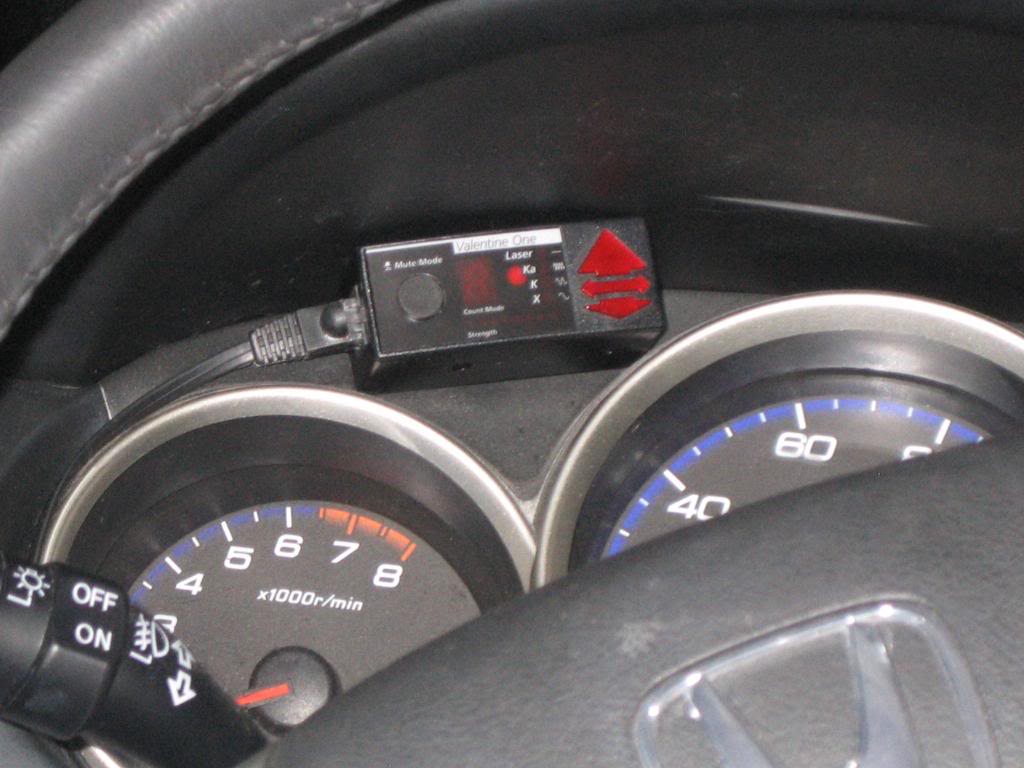
1. Valentine 1 Radar Detector
2. Valentine 1 Concealed Display
3. Garmin Nuvi 265T
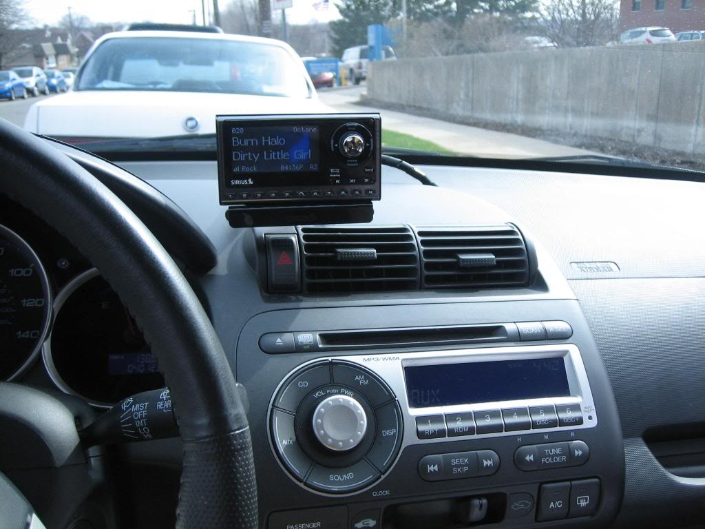
4. Sirius Sportster 5
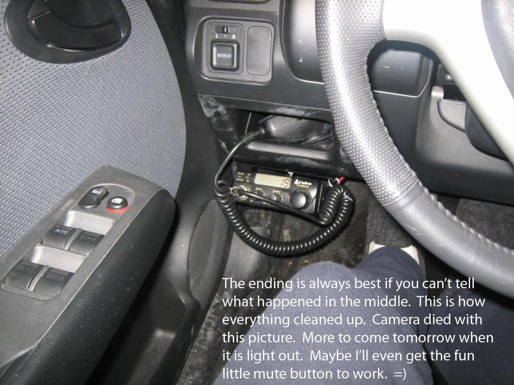
5. Cobra 19 Ultra III CB Radio
6. RS Pro-94 Scanner
All of these items are hard-wired to switches. The switches are located in the little well just to the right of the e-brake. First things first, the hard-wiring technique. You�ll notice that all of the items above have DC (cigarette lighter) adapters. However, my Fit only came from the factory with one of those plugs and I�d prefer to leave it for that once in a while case where I need to plug something in.
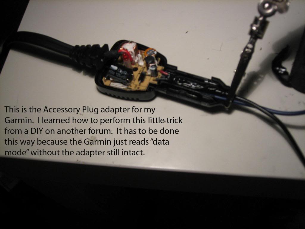
This is how you hardwire a cigarette lighter adapter. Some people will say �Hey, why not just cut the plug off and use butt connectors?� With some devices such as Garmin Nav systems, there is a chip (seen below) in the plug that must be left in-line otherwise the device will just read �data mode.�
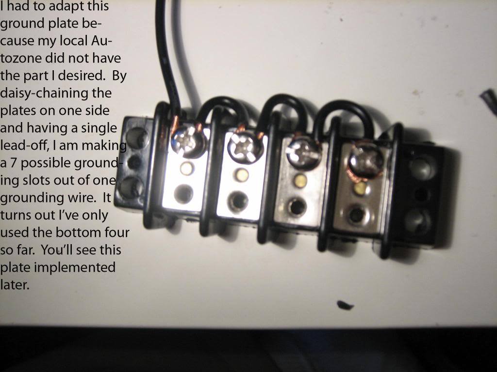
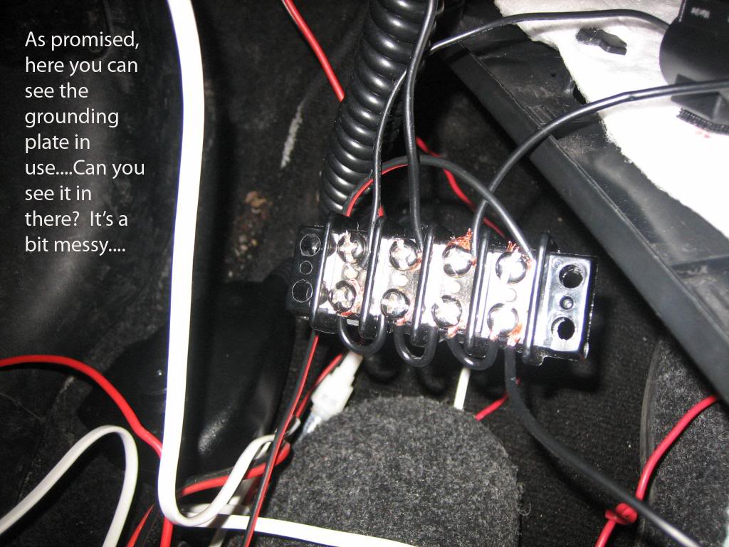
After that I made a ground junction so I could funnel all my ground wires into one. This PROBABLY wasn't a great idea due to the transitivity of grounding if one item were to ground out, but the fit is NOT a large car with a plethora of grounding points!
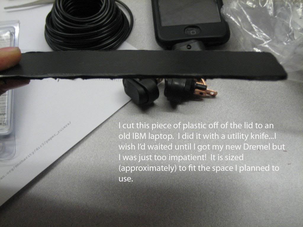
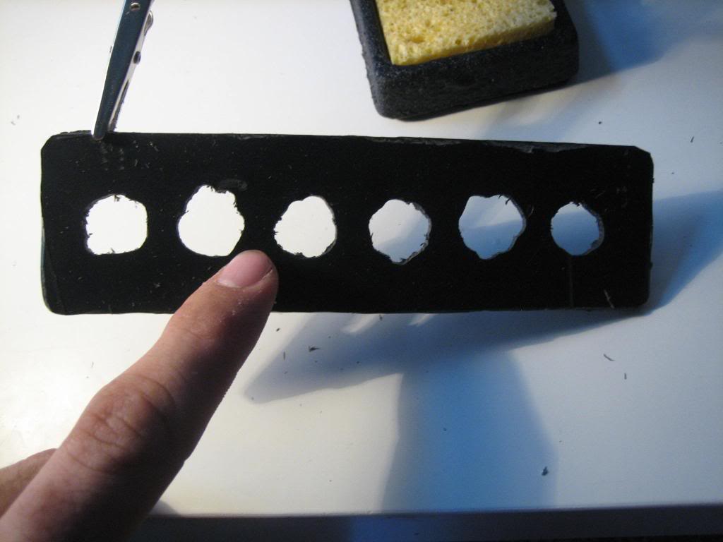
I used this piece of plastic:
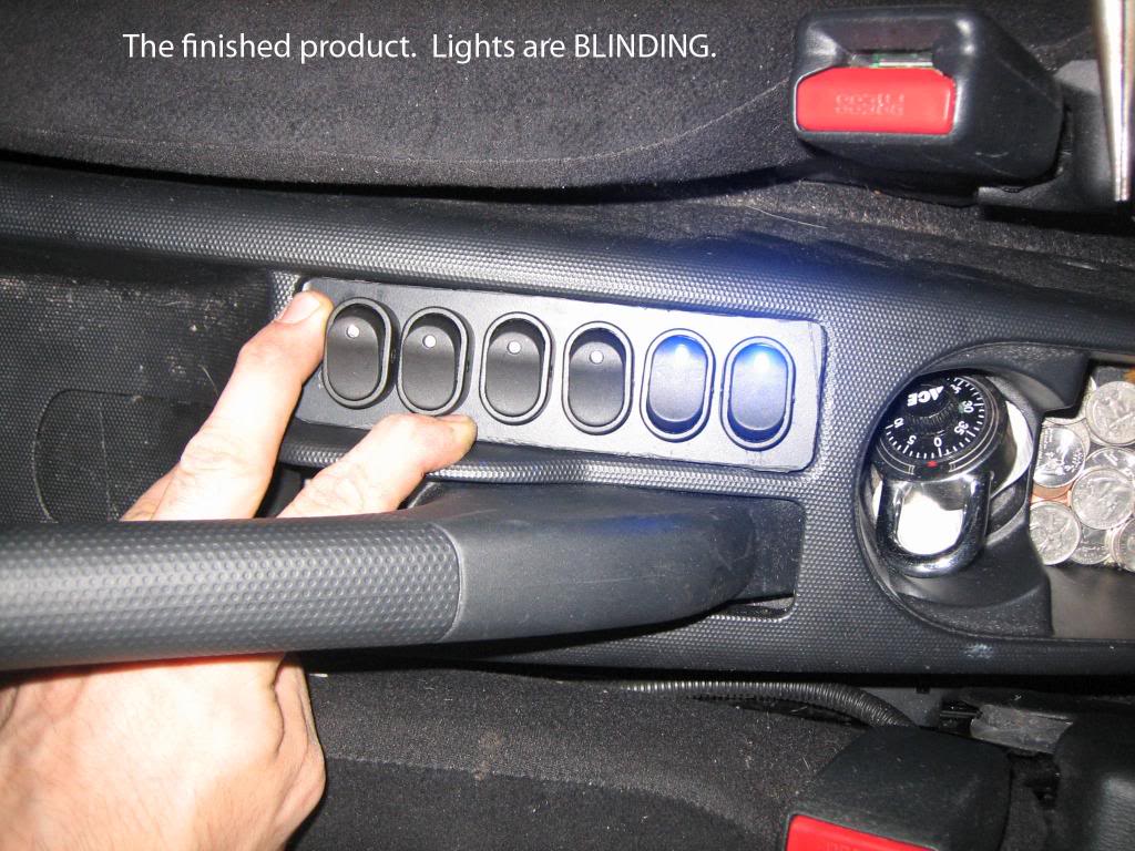
To create a switch panel seen here:
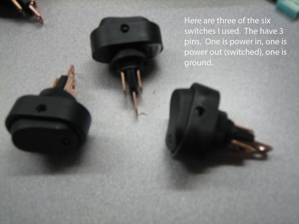
And added the switches....a few of which can be seen here:
I made some new power wires to run from my fuse box:
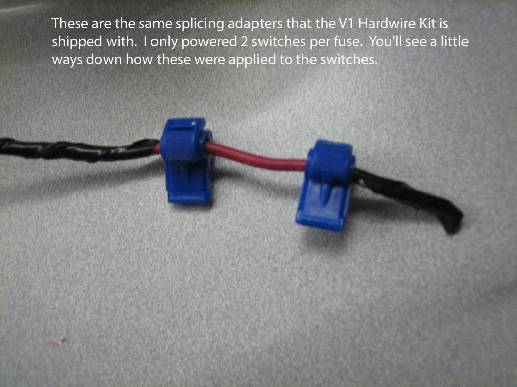
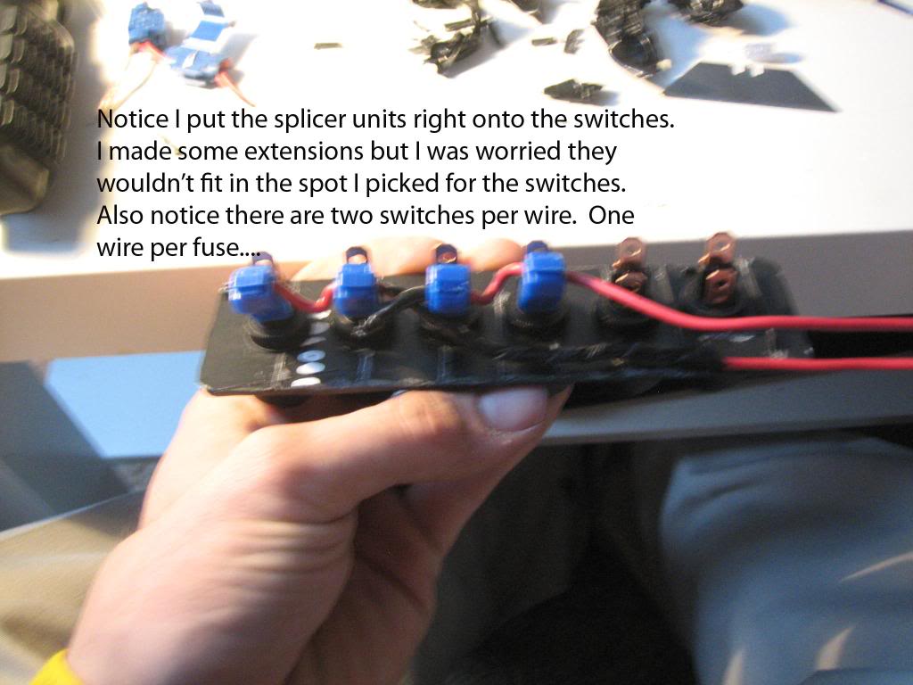
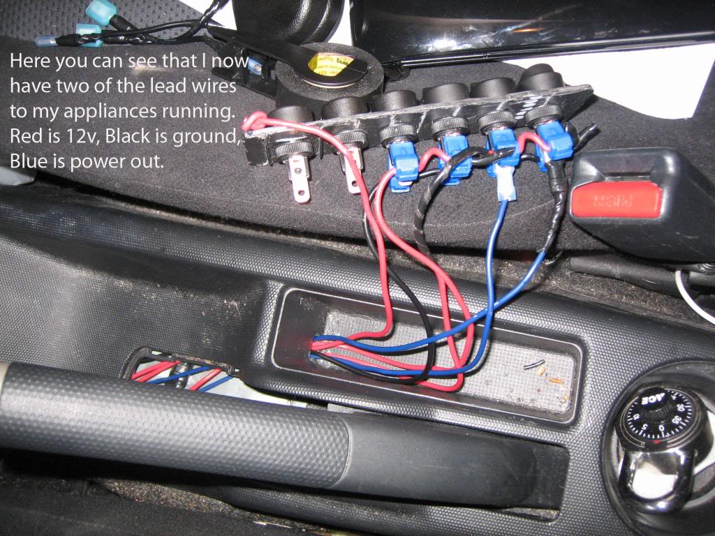
I attached said power wires to the switches on my panel like so:
I ran the ground wire for the switches next. Again, I used one continuous wire across all the switches. This probably is NOT a good idea. I would recommend coming up with a different way to ground your system.
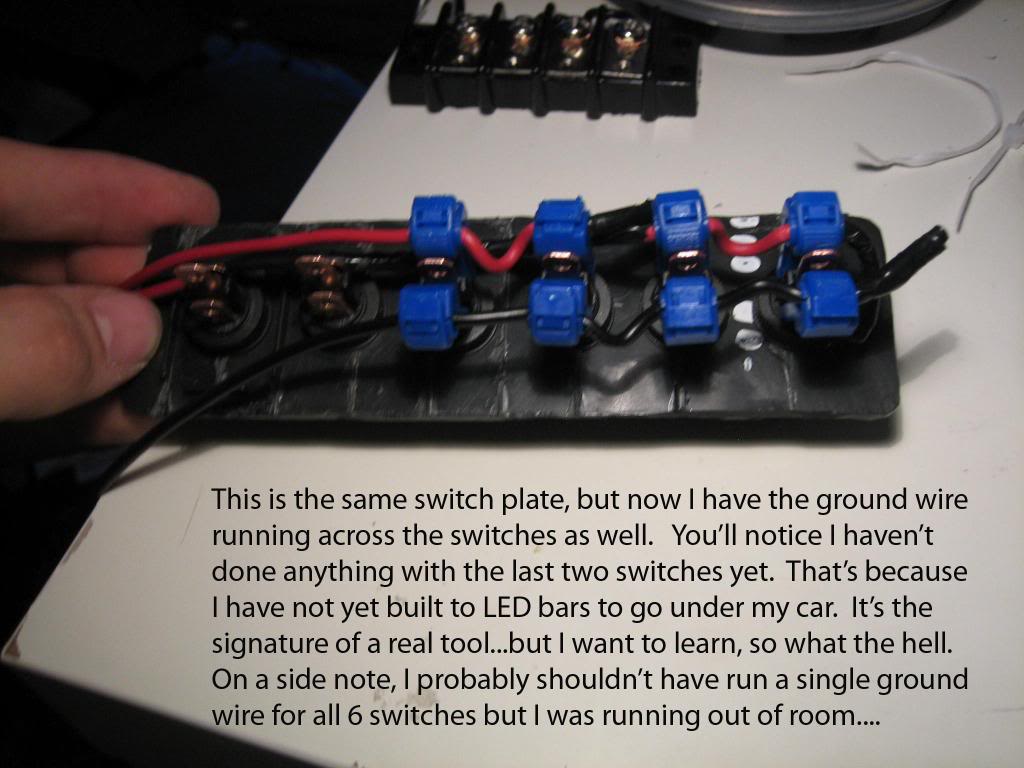
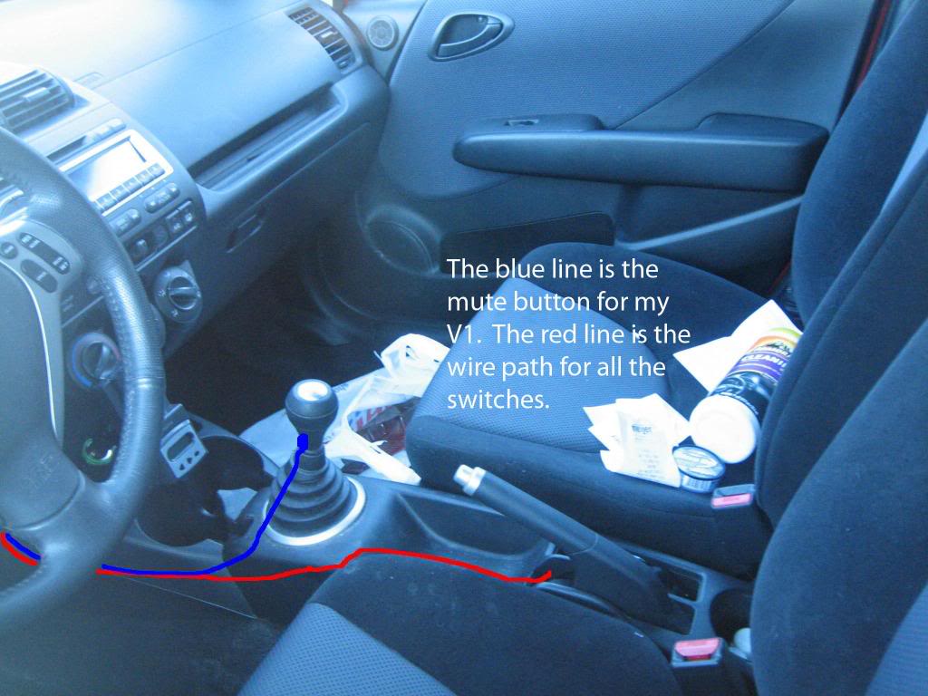
I ran the 3 power wires, 1 ground wire, and 5 (so far) accessory wires from my new switch panel location (next to the E-Brake) to their various destinations. As many of you know, it is not hard to hide wires in the Fit. Most panels are snap-clicked in place and can be removed with a firm hand.
Look at the following to see where the wires run:
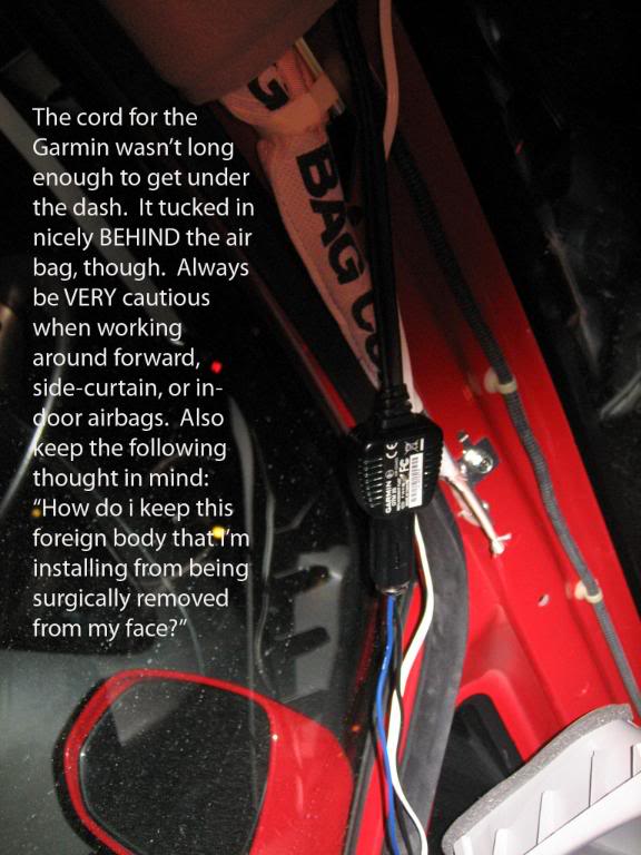
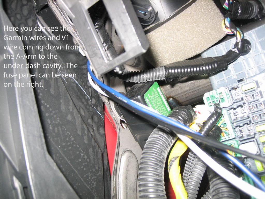
I ran the phone cord and power cable for my V1 and Garmin down from the roof. The Garmin wire wasn't long enough to get under the dash, though, so I had to hide it in the A-Frame as seen here:
The wires continued down the A-Frame and under the dash. Here is a rough pic of them coming down from behind the vents:
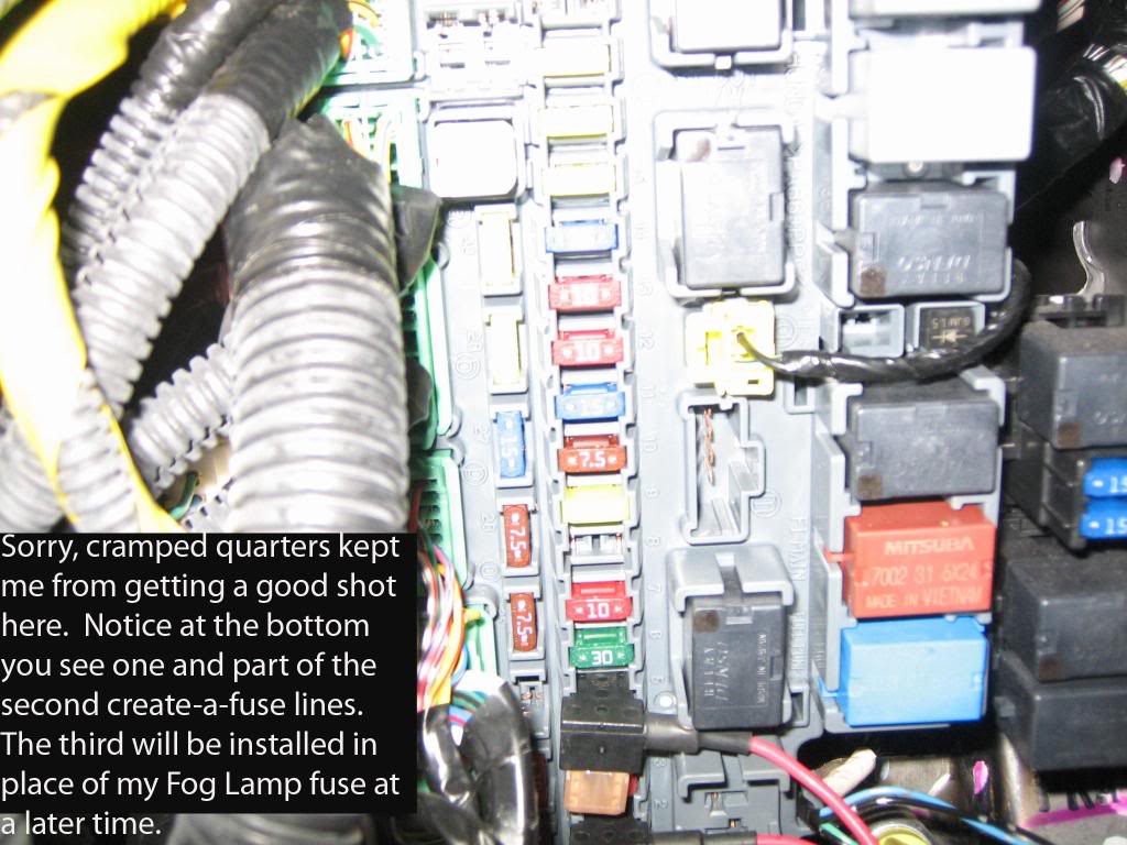
As I said before, I split up the 6 switches into 3 different fuse relays. Here you can see 2:
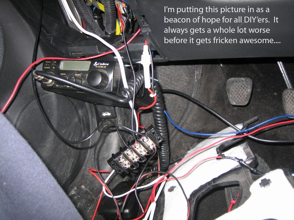
I spent 20-30 minutes making sense of all the wires, taping, grounding, and organizing....
Here is my new switch panel:
And here is a picture just to prove I do indeed clean up after myself:
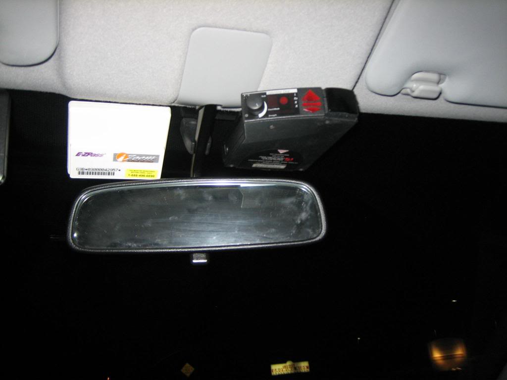
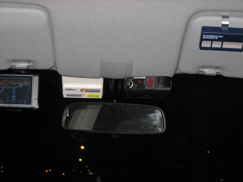
Here are a few pictures of the semi-final setup:
If you didn�t realize it already, all of the pictures up to this point were from a DIY that I posted for another forum. (www.radardetector.net) That forum is based mainly on radar detector installation, optimization, and concealment. Below are some things that I�ve added since I made that DIY.
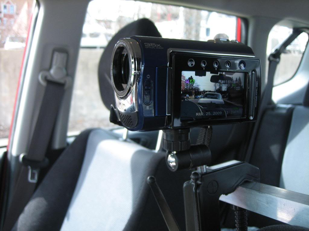
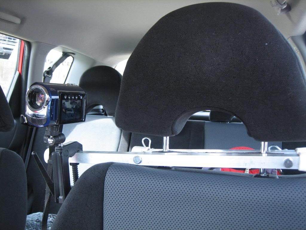
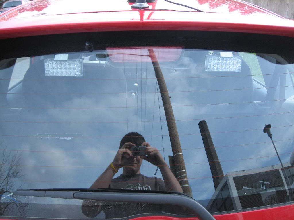
Firstly, the camera:
I went to Home Depot and picked up some 1� x 1� aluminum tubing, some rubber grab mat, stool �feet�, and some multi-position cotter bolts. I ordered the actual camera mount from China. It�s VERY cheap.
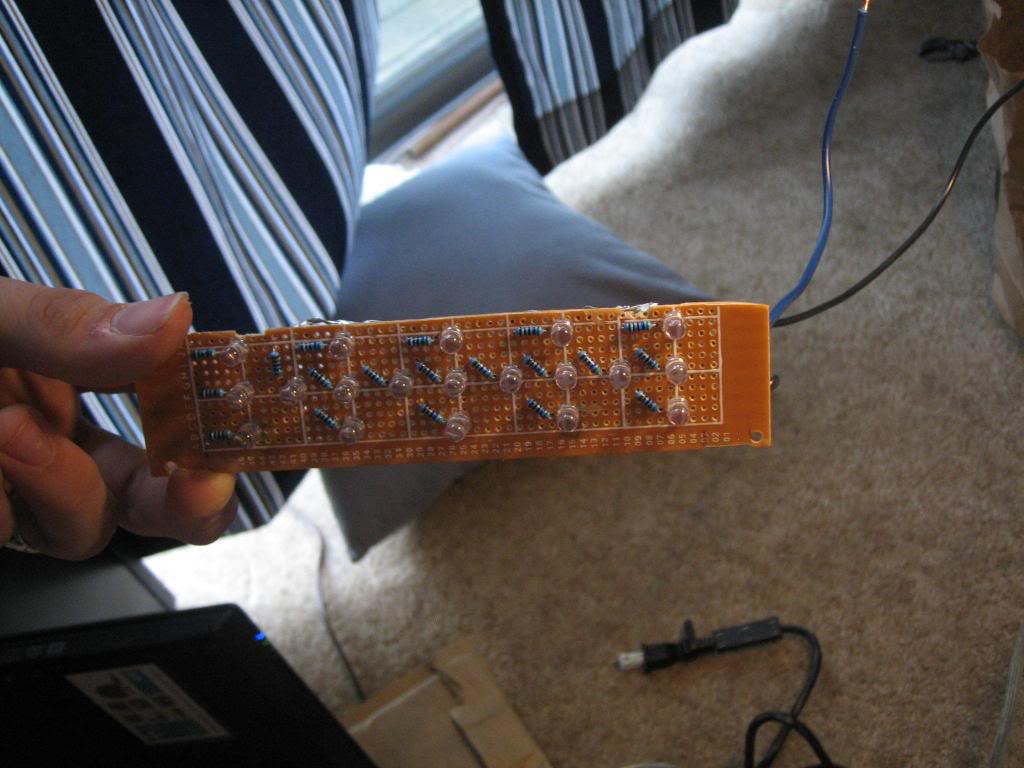
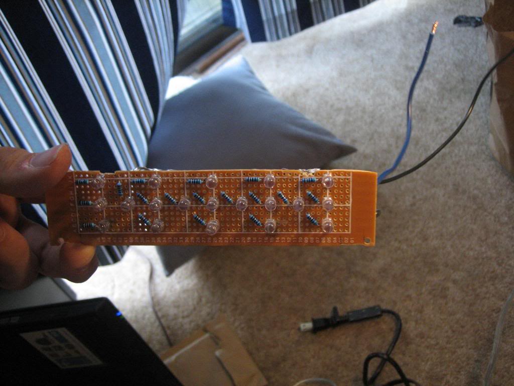
I put some LEDs in the back window with some look-alike flash patterns. They flash in a very blue-looking white. These are�umm�for safety. =)
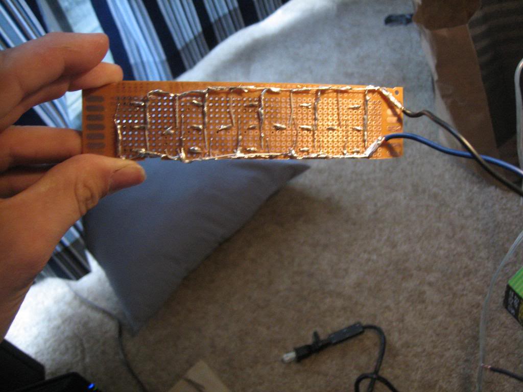
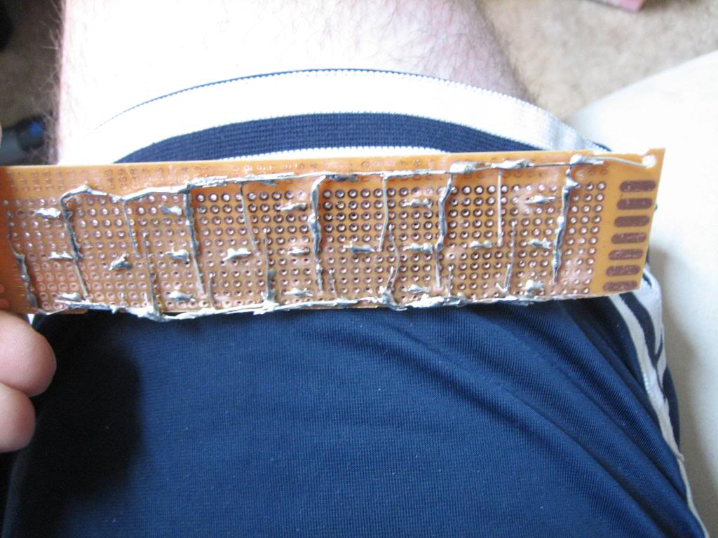
I branched out a bit from the JDM Third Brake Light DIY but it came in very useful. Below are some pictures of the LED board that I made to fit in the housing. Unfortunately the only Prototyping board that I had on hand did not have and rails so I had to make them�REALLY janky, I know.
Scanners are illegal to monitor inside a vehicle in my state (Indiana) without a HAM License or unless �You are a professional news-gathering official whose purpose in using such radio devices is to better gather news for distribution to the public.� Yada yada yada. Seeing as how I have/am neither�it�s hidden and won�t be shown in any pictures. =)
I�ve got some more pictures to add of my Short Ram Intake (modeled from Sid�s DIY), my auxiliary grounding cable (also modeled from a DIY here), my air horn (yes, you read that right), and my PA speaker that I operate via the CB. Check back soon. =)
Please DO NOT hesitate to post questions, request more pictures, more in-depth explanation, or otherwise. I didn�t go through all of the trouble of organizing these pictures to show off. My head is big enough already. ;-)
-Rob
The following is provided as a GUIDE ONLY, and neither myself, nor FITFREAK.NET endorse, recommend, encourage nor take any responsibility for the outcome of someone else doing the following. You follow these steps at your own risk!
I often find that when I�m looking through forums I see things that are off-topic that I would like to know more about. As forum etiquette dictates, de-railing the thread would be rude and PMs often are not answered. SO�.I�ve started this thread as an outline of the things I�ve done to my vehicle. Eventually it will turn into one big DIY for several different things, but for now hopefully these pictures will at least inspire some interest.
Firstly, here is a list of the components of my aftermarket electronics install:
1. Valentine 1 Radar Detector
2. Valentine 1 Concealed Display
3. Garmin Nuvi 265T
4. Sirius Sportster 5
5. Cobra 19 Ultra III CB Radio
6. RS Pro-94 Scanner
All of these items are hard-wired to switches. The switches are located in the little well just to the right of the e-brake. First things first, the hard-wiring technique. You�ll notice that all of the items above have DC (cigarette lighter) adapters. However, my Fit only came from the factory with one of those plugs and I�d prefer to leave it for that once in a while case where I need to plug something in.
This is how you hardwire a cigarette lighter adapter. Some people will say �Hey, why not just cut the plug off and use butt connectors?� With some devices such as Garmin Nav systems, there is a chip (seen below) in the plug that must be left in-line otherwise the device will just read �data mode.�
After that I made a ground junction so I could funnel all my ground wires into one. This PROBABLY wasn't a great idea due to the transitivity of grounding if one item were to ground out, but the fit is NOT a large car with a plethora of grounding points!
I used this piece of plastic:
To create a switch panel seen here:
And added the switches....a few of which can be seen here:
I made some new power wires to run from my fuse box:
I attached said power wires to the switches on my panel like so:
I ran the ground wire for the switches next. Again, I used one continuous wire across all the switches. This probably is NOT a good idea. I would recommend coming up with a different way to ground your system.
I ran the 3 power wires, 1 ground wire, and 5 (so far) accessory wires from my new switch panel location (next to the E-Brake) to their various destinations. As many of you know, it is not hard to hide wires in the Fit. Most panels are snap-clicked in place and can be removed with a firm hand.
Look at the following to see where the wires run:
I ran the phone cord and power cable for my V1 and Garmin down from the roof. The Garmin wire wasn't long enough to get under the dash, though, so I had to hide it in the A-Frame as seen here:
The wires continued down the A-Frame and under the dash. Here is a rough pic of them coming down from behind the vents:
As I said before, I split up the 6 switches into 3 different fuse relays. Here you can see 2:
I spent 20-30 minutes making sense of all the wires, taping, grounding, and organizing....
Here is my new switch panel:
And here is a picture just to prove I do indeed clean up after myself:
Here are a few pictures of the semi-final setup:
If you didn�t realize it already, all of the pictures up to this point were from a DIY that I posted for another forum. (www.radardetector.net) That forum is based mainly on radar detector installation, optimization, and concealment. Below are some things that I�ve added since I made that DIY.
Firstly, the camera:
I went to Home Depot and picked up some 1� x 1� aluminum tubing, some rubber grab mat, stool �feet�, and some multi-position cotter bolts. I ordered the actual camera mount from China. It�s VERY cheap.
I put some LEDs in the back window with some look-alike flash patterns. They flash in a very blue-looking white. These are�umm�for safety. =)
I branched out a bit from the JDM Third Brake Light DIY but it came in very useful. Below are some pictures of the LED board that I made to fit in the housing. Unfortunately the only Prototyping board that I had on hand did not have and rails so I had to make them�REALLY janky, I know.
Scanners are illegal to monitor inside a vehicle in my state (Indiana) without a HAM License or unless �You are a professional news-gathering official whose purpose in using such radio devices is to better gather news for distribution to the public.� Yada yada yada. Seeing as how I have/am neither�it�s hidden and won�t be shown in any pictures. =)
I�ve got some more pictures to add of my Short Ram Intake (modeled from Sid�s DIY), my auxiliary grounding cable (also modeled from a DIY here), my air horn (yes, you read that right), and my PA speaker that I operate via the CB. Check back soon. =)
Please DO NOT hesitate to post questions, request more pictures, more in-depth explanation, or otherwise. I didn�t go through all of the trouble of organizing these pictures to show off. My head is big enough already. ;-)
-Rob

Dude. Just take the ham radio exam, anymore it's no-code.
OR: create a news-blog, and put a sticker with the link on your car. You won't even have to update it.
Nice job though on the finished product, it looks clean. How'd you route your antenna coax?
OR: create a news-blog, and put a sticker with the link on your car. You won't even have to update it.
Nice job though on the finished product, it looks clean. How'd you route your antenna coax?
The antenna coax enters the "shell" of the car at the back door, runs down to the right along the weatherstripping and just gets sandwiched between the door and the weatherstripping at the bottom. Please note that the wire is still "outside" the car as it wraps down to the right because if I sandwiched it at the top it would allow rain to easily drip into the vehicle. By leaving it "outside" until it gets to the bottom edge of the door/weatherstripping you're allowing gravity to keep most of the weather hazards from happening. Once it jumps the weatherstripping it goes right under the plastic. It runs through the spare tire well toward the right side of the car. You can see a snippet of it as it comes out beside the right rear seat before going under the door molding plastic. It goes under the door molding plastic (the kick plate) of the back door, comes out beside the front passenger seat, goes under it and into the console plastic. From there it runs forward through the console to the dash. It actually terminates right behind the HVAC and I have a splitter there that sends a lead to my CB and Scanner so they both use the same one.
The only downfall that this routing has is that it "jumps" the weatherstripping at the back door. I wish there was a more weather-proof way for it to enter the car but short of going under the car and drilling into the spare-tire well, I couldn't think of anything. The wire was too thick to go under/behind the weatherstripping.
Sorry for my tardy response. =)
rc
So far so good
I haven't had any problems yet. I'm not entirely worried about it at the moment. All of the agencies in my area are within the 5-year locale switch for freqs. Currently some are digital, the interesting ones are not...so untilI have a $500 scanner hooked up, I'm not worried.
rc
rc

Thread
Thread Starter
Forum
Replies
Last Post
JDMchris.com
2nd Generation GE8 Specific DIY: Repair & Maintenance Sub-Forum
0
Jul 2, 2010 11:05 PM
kamakurakid
Fit DIY: Repair & Maintenance
10
Feb 19, 2009 12:00 PM
DC_Native
Fit Suspension & Brake Modifications
3
Sep 22, 2007 03:31 PM