
Heated Seats

Thread Starter
|
Member
Joined: Feb 2010
Posts: 176
From: Richmond, VA
Heated Seats
I installed my heated seats this weekend (Driver & Passenger). I ahve Clazzio seat covers which made the install relatively painless. The OEM cloth covers are glued down I believe so i'm sure it would be significantly more difficult that way.
Anyay, I ordered these carbon heating pads for $100 shipped (both seats):
2 seat Carbon Fiber Universal Heated Seat Heater Kit - eBay (item 170479355909 end time Dec-25-10 05:21:06 PST)
They are really nice quality. The pads are very flexible and you don't notice them at all. Sorry i dint have my camera when I installed them They look like cotton sheets with double stick tape on the back and a wire exiting from one end. I just put them in between the seat and the Clazio cover. I did remove the seats from the car to better rout the wires both under the seat and under the carpet.
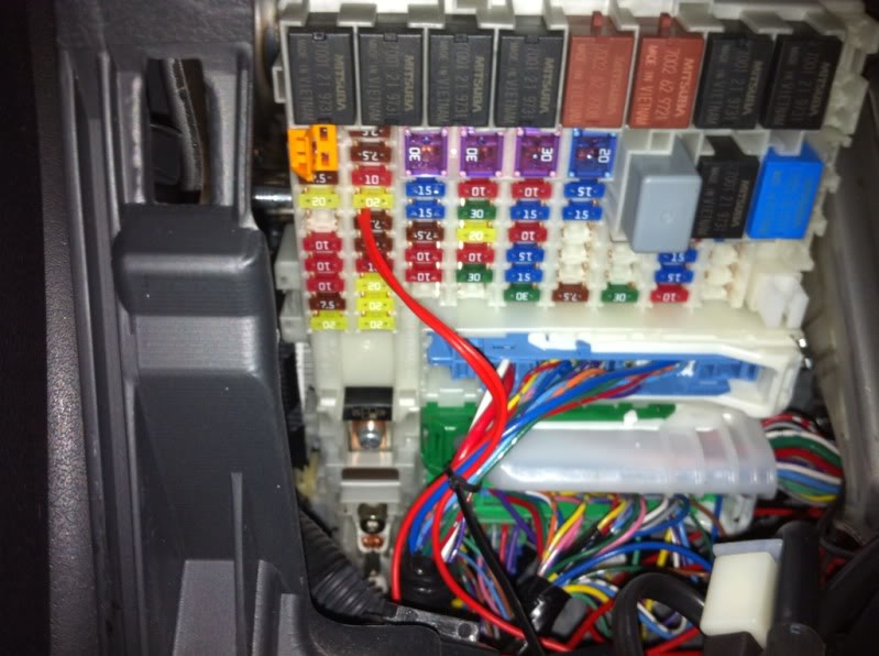
I wired these up to the switched 20 Amp ACC circuit in the fuse panel using an Add-A-Circuit type adapter. Each seat has 10amp fuses already so this circuit will be fine.
I'm very happy with these units. The quality is very nice all the wiring is properly soldered in place and looks durable. They heat up after about 3-4 mins and have high and low settings.
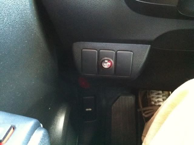
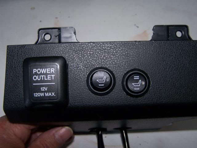
Here is where I have the switches:
Driver:
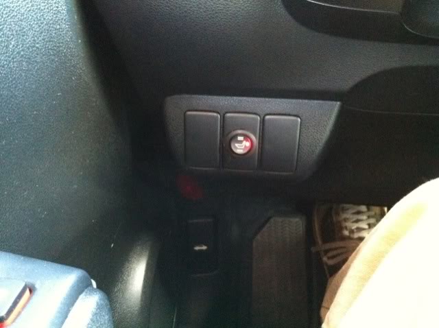
Passenger:
Anyay, I ordered these carbon heating pads for $100 shipped (both seats):
2 seat Carbon Fiber Universal Heated Seat Heater Kit - eBay (item 170479355909 end time Dec-25-10 05:21:06 PST)
They are really nice quality. The pads are very flexible and you don't notice them at all. Sorry i dint have my camera when I installed them
They look like cotton sheets with double stick tape on the back and a wire exiting from one end. I just put them in between the seat and the Clazio cover. I did remove the seats from the car to better rout the wires both under the seat and under the carpet.I wired these up to the switched 20 Amp ACC circuit in the fuse panel using an Add-A-Circuit type adapter. Each seat has 10amp fuses already so this circuit will be fine.
I'm very happy with these units. The quality is very nice all the wiring is properly soldered in place and looks durable. They heat up after about 3-4 mins and have high and low settings.
Here is where I have the switches:
Driver:
Passenger:

Last edited by jcuecker; Dec 6, 2010 at 06:11 PM.

A very neat installation. I am sure the butt appreciates it as the Clazzios are a bit chilly in the morning.
Rather than going right to the fuse box I think you could splice into the PURPLE ACC wire right behind the ACC outlet panel. I am only suggesting this as in my case I have a mess of spices at the fuse panel for my footwells and signal mirrors.
Rather than going right to the fuse box I think you could splice into the PURPLE ACC wire right behind the ACC outlet panel. I am only suggesting this as in my case I have a mess of spices at the fuse panel for my footwells and signal mirrors.
I just recd mine. Anyone else install these? If so any other tips/suggestions?
As no instructions I assume the black wire is to be grounded and the hot red wire to the purple accessory wire will work.
As no instructions I assume the black wire is to be grounded and the hot red wire to the purple accessory wire will work.
I started project this morning.
My Classios slid out nice and easy to install pads on the passenger side. Unfortunately I undid the straps on the bottom of the Classios and now can`t figure out the pattern to thread them and tighten.
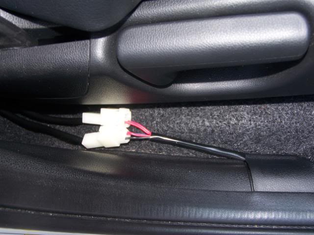
I ran the wires to the side and around bottom of the seat. I am going to wrap those connectors real well with black tape. I have run the wires along door sill under the trim and up the front to just below the glove box. and stopped. It was getting warm.
Also it looks like the cable with switch is not going to be long enouigh to reach to drivers side. I wanted both switches over there. We may just extend all four wires on the switch.
Some interim pics.
Wiring coming out from center of seat and around the corner. I will adjust the amount of slack once all hooked up.
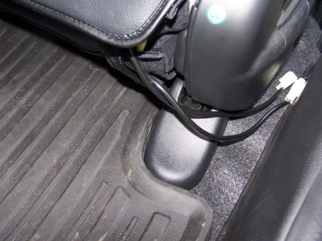
Side of seat. This is what will be wrapped in tape.
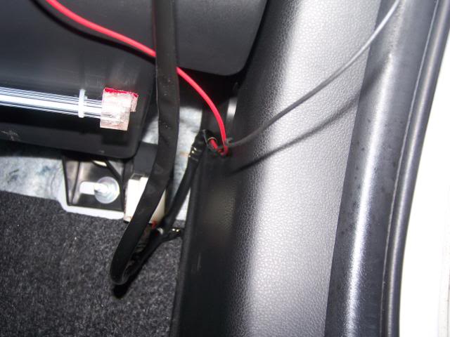
Disappearing up to glove box area.
My Classios slid out nice and easy to install pads on the passenger side. Unfortunately I undid the straps on the bottom of the Classios and now can`t figure out the pattern to thread them and tighten.
I ran the wires to the side and around bottom of the seat. I am going to wrap those connectors real well with black tape. I have run the wires along door sill under the trim and up the front to just below the glove box. and stopped. It was getting warm.
Also it looks like the cable with switch is not going to be long enouigh to reach to drivers side. I wanted both switches over there. We may just extend all four wires on the switch.
Some interim pics.
Wiring coming out from center of seat and around the corner. I will adjust the amount of slack once all hooked up.
Side of seat. This is what will be wrapped in tape.
Disappearing up to glove box area.
Changed plan. Now the wiring comes out the back of the seats around to the console. The wiring will slide up under the sides quite easily.
Removing cup holder gives access to area over shifter where the thermostats and in line fuse boxes can be place.
I made booboo drilling holes for switches and got them off centered. It will be easy to redo.
Seeing the purple hot wire and black ground right there that is needed to wire to gave me idea. I knew I could not get into the actual wires as there is just no slack to pull that connector out further to work on. I am going to get some spade connectors and make up a short say 3-4 inch harness with the heat pad wires connected in. It should all fit in. There is way too much wiring but as so many wires I am just going to coil and tie up vs trying to shorten them.
Oh a tip to pull that panel with the outlet. Make a little hook from coat hanger and using pliers pull hard on TOP edge.
There is a nice ground bolt way down in the hole but it has some weird hex top so I could not use it. Besides can only get one hand in there so would likely end up with the exisitng ground wires disconnected and a mess.
The seat pads went in OK. The Clazzios are stretched enough that they slid up easily. Nothing like putting them on the first time. Be careful when removing the tape from the pads. That adhesive sticks to everything. Also move the pads back far enough so that the small square plastic piice inside where the wires connect is down in between seats enough so you will not be sitting/leaning on them.
So far it has not been that difficult. Just time consuming. Been at it for a couple hours the last two mornings. I quit when getting tired vs f***ing it up. That only comes with age guys.
Will post again when finished.
Some pics
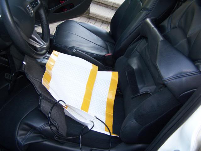
The pads and Clazzios pulled back. Geez that original upholstery is ugly.
Panel with switches in. Note had to drill holes in the bottom to drop wires through as well.
The messed up panel. But it does sit back enough not that noticeable and I usually have something in cupholder.
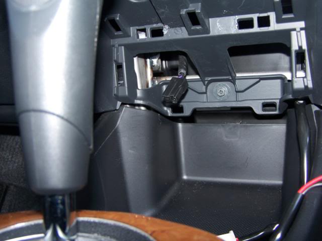
The hole. Can see the connector for outlet I will be connecting to.
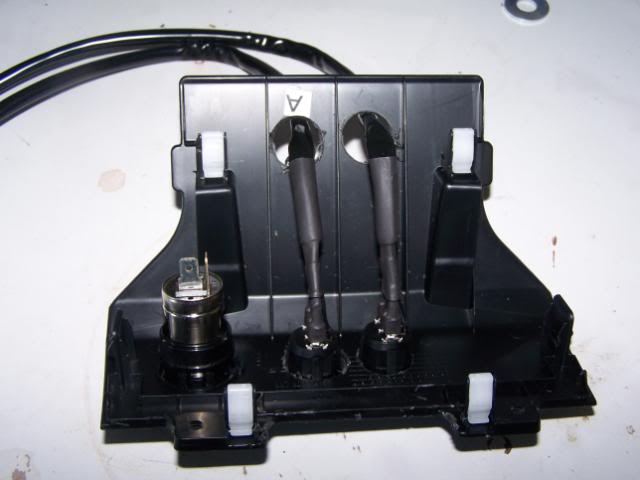
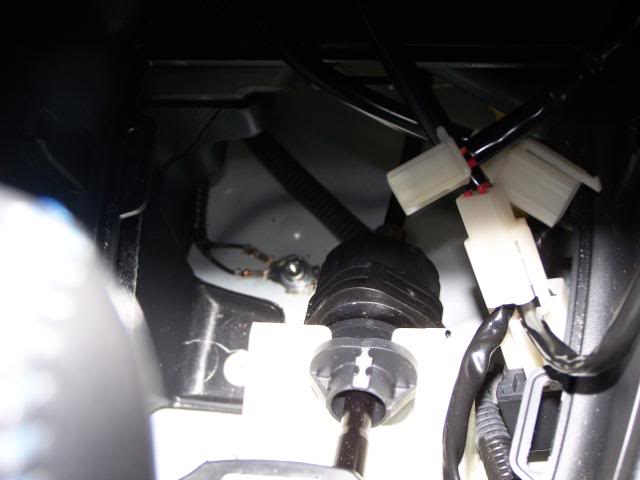
The hole where fuse boxes and thermostat will be place. You can see that goground screw down there with two black wires. The white things are some of connectors for pads.
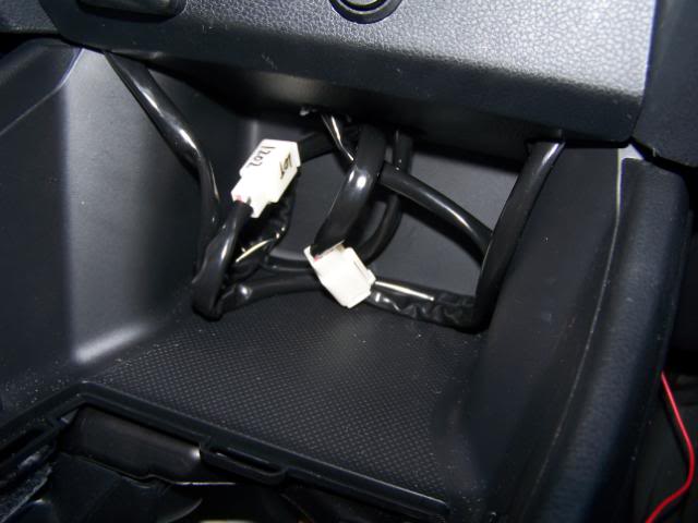
Some of the wiring dropped down from switches. It will have to be pulled back down under the sides of console to finish it up.
Removing cup holder gives access to area over shifter where the thermostats and in line fuse boxes can be place.
I made booboo drilling holes for switches and got them off centered. It will be easy to redo.
Seeing the purple hot wire and black ground right there that is needed to wire to gave me idea. I knew I could not get into the actual wires as there is just no slack to pull that connector out further to work on. I am going to get some spade connectors and make up a short say 3-4 inch harness with the heat pad wires connected in. It should all fit in. There is way too much wiring but as so many wires I am just going to coil and tie up vs trying to shorten them.
Oh a tip to pull that panel with the outlet. Make a little hook from coat hanger and using pliers pull hard on TOP edge.
There is a nice ground bolt way down in the hole but it has some weird hex top so I could not use it. Besides can only get one hand in there so would likely end up with the exisitng ground wires disconnected and a mess.
The seat pads went in OK. The Clazzios are stretched enough that they slid up easily. Nothing like putting them on the first time. Be careful when removing the tape from the pads. That adhesive sticks to everything. Also move the pads back far enough so that the small square plastic piice inside where the wires connect is down in between seats enough so you will not be sitting/leaning on them.
So far it has not been that difficult. Just time consuming. Been at it for a couple hours the last two mornings. I quit when getting tired vs f***ing it up. That only comes with age guys.
Will post again when finished.
Some pics
The pads and Clazzios pulled back. Geez that original upholstery is ugly.
Panel with switches in. Note had to drill holes in the bottom to drop wires through as well.
The messed up panel. But it does sit back enough not that noticeable and I usually have something in cupholder.
The hole. Can see the connector for outlet I will be connecting to.
The hole where fuse boxes and thermostat will be place. You can see that goground screw down there with two black wires. The white things are some of connectors for pads.
Some of the wiring dropped down from switches. It will have to be pulled back down under the sides of console to finish it up.
I am done and got warm butt.
Did not take more pics. I made up two short wiring harnesses in Y shape. Plugged one end into the socket with the black wire. The other ends went to the outlet ground post and the ground wire from the seats pads. Then did the same to the hot wire. A huge excess of wire. I bundled as best I could and stuck it down under the cup holder. I was then able to get both clips on the holder to fasten.
Did not take more pics. I made up two short wiring harnesses in Y shape. Plugged one end into the socket with the black wire. The other ends went to the outlet ground post and the ground wire from the seats pads. Then did the same to the hot wire. A huge excess of wire. I bundled as best I could and stuck it down under the cup holder. I was then able to get both clips on the holder to fasten.


New Member
Joined: Dec 2010
Posts: 1
From: Bowling Green, KY
I went the simplest route I could in regards to wiring. I twisted both red wires together and seated them in the fuse slot for the 20amp ACC fuse. I used the fuse that was already there to wedge the wires in place. Found a bolt close by to ground the black wires and voila.
I went the simplest route I could in regards to wiring. I twisted both red wires together and seated them in the fuse slot for the 20amp ACC fuse. I used the fuse that was already there to wedge the wires in place. Found a bolt close by to ground the black wires and voila.
You could have used an Add A Fuse in the fuse box for a bit neater install. I put one in there to connect the LEDs under my headlights.
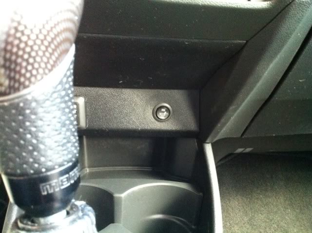
I installed these and put the switches in the center JDM console.
P1010001 | Flickr - Photo Sharing!
P1010001 | Flickr - Photo Sharing!

I installed these and put the switches in the center JDM console.
P1010001 | Flickr - Photo Sharing!
P1010001 | Flickr - Photo Sharing!
You mean warm. How often do you have rear seat passengers? I do not see any problem doing it. The switches may mount at the rear of the console?

You can use pretty much any power source for the seats. Mine are connected to the Aux circuit.

From an old post of mine, see below:
I know you got the mod done, but just as a curiosity I decided to compare these with the GE8 ESM (the one from the thread).
For one version of the Japanese GE8 (some of these features are dependent on what options are on the car)... different locations for the Thai made & other versions.
For one version of the Japanese GE8 (some of these features are dependent on what options are on the car)... different locations for the Thai made & other versions.
- 31 - 7.5 A - Engine oil sensor
- 40 - 20 A - Driver's seat heater (Via driver's seat heater relay), Front passenger's seat heater (Via front passenger's seat heater relay)
- 41 - 10 A - Front position lights (Via daytime running lights relay), Taillights (Via daytime running lights relay), License plate lights (Via daytime running lights relay)
- 45 - 15 A - Driver's door unlock relay, Fuel lid actuator (Via driver's door unlock relay), Driver's door lock actuator (Via driver's door unlock relay)
- 45 - 20 A - Front super locking relay, Rear super locking relay, Driver's super locking actuator (Via front super locking relay), Passenger's super locking actuator (Via front super locking relay), Right rear super locking actuator (Via rear super locking relay), Left rear super locking actuator (Via rear super locking relay)
- 46 - 20 A - Sunshade motor/control unit
- 53 - 10 A - Transmission control module (i-SHIFT system)
- 54 - Rear Defogger (if equipped)
- 55 - Heated Mirror (if equipped)