
Help - Remote Starter Install - Manual - Bulldog Deluxe 500


Thread Starter
|
New Member
Joined: Mar 2012
Posts: 7
From: 19047
Help - Remote Starter Install - Manual - Bulldog Deluxe 500
I�m installing a remote starter on my fit and am having a few issues. I was going to post an install guide for fits, since I had difficulty finding specific info on remote starter installs for them, but I have some questions for anyone that can help. I will use abbreviations to keep this neat.
Car: Honda Fit 2011 Sport MT (US)
Remote Starter (RS): Bulldog Model Deluxe 500 Remote Starter with Keyless Entry (2 way LCD remote starter with keyless entry)
Immobilizer Bypass Module (IBM): Omega OL-DB-HA (flashed for Honda Fit, I also have a iDatalink ADS- DLSL-HA which is for another fit I�m doing next); Both have been flashed for a honda fit 2009-2011 (The installer I bought them from mailed me the printed flashed logs with the bypasses after he flashed them)
Yes it�s a MT. I installed a magnetic reed switch and rare earth magnet under the clutch to ground the Neutral Safety Switch wire when in neutral. I�ve tested this circuit with an LED for a week before installing it, and the circuit works as it should.
Diagrams & Manuals:
Bulldog
Install Manual:
http://www.bulldogsecurity.com/manua...lmanuallow.pdf
Owner�s Manual:
http://www.bulldogsecurity.com/manua...uallow4-11.pdf
Quick Install Troubleshooting diagrams and wiring harnesses:
http://www.bulldogsecurity.com/manualsnew/deluxe500QuickStart1FINALlow.pdf
Wiring Diagram:
Vehicle wiring diagrams
Omegalink: OL-DB-HA:
Omegaweblink
iDatalink ADS-DLSL-HA: (same as Omega)
iDatalink - Product Search Results
Wiring:
WIRING CHART FROM BULLDOG:
PART/ COLOR/ LOCATION
12 VOLT CONSTANT / WHITE (+) @ / IGNITION SWITCH, (BROWN, 7- Pin Plug) Pin 3
STARTER / PINK (+) / @ IGNITION SWITCH, (BROWN, 7- Pin Plug) Pin 1
STARTER 2 / N/A
IGNITION 1 / YELLOW (+) / @ IGNITION SWITCH, (BROWN, 7- Pin Plug) Pin 6
IGNITION 2 / N/A
IGNITION 3 / N/A
ACCESSORY/HEATER BLOWER 1 / ORANGE (+) /@ IGNITION SWITCH, (BROWN, 7- Pin Plug) Pin 4
ACCESSORY/HEATER BLOWER 2 / RED (+) / @ IGNITION SWITCH, (BROWN, 7- Pin Plug) Pin 5
KEYSENSE / N/A
PARKING LIGHTS (-) / GRAY (-) / @ HEADLIGHT SWITCH, (BLACK/WHITE, 12-Pin Plug) Pin 11
PARKING LIGHTS (+) / GRAY (+) / @ DASH FUSE BOX, (GREEN/WHITE, 49-Pin Plug) Pin 42
POWER LOCK / LIGHT BLUE (TYPE B) / @ DASH FUSE BOX, (LT.GREEN, 12-Pin Plug) Pin 8
POWER UNLOCK / GRAY (TYPE B) / @ DASH FUSE BOX, (LT.GREEN, 12-Pin Plug) Pin 1
DOOR TRIGGER / BLUE (-) / @ DASH FUSE BOX, (GREEN/WHITE, 49-Pin Plug) Pin 33
DOMELIGHT SUPERVISION / BLUE (-) / @ DASH FUSE BOX, (LT.GREEN, 8- Pin Plug) Pin 7
TRUNK RELEASE / (LOCKS/UNLOCKS with Doors)
SLIDING POWER DOOR / N/A
HORN / ORANGE (-) @ / HORN SWITCH, (WHITE, 20-Pin Plug) Pin 1
TACH / any BROWN, RED, BLUE or YELLOW (AC) / @ FUEL-INJECTOR Harness, on Drivers side of Engine
WAIT TO START LIGHT / N/A
BRAKE / LIGHT GREEN (+) / @ BRAKE SWITCH or DASH FUSE BOX, (GREEN/WHITE, 49-Pin Plug) Pin 14
FACTORY ALARM DISARM / GREEN (-), NOTE #2 / @ DASH FUSE BOX, (LT.GREEN, 12-Pin Plug) Pin 4
ANTI-THEFT / HONDA'S TRANSPONDER SYSTEM, See NOTE #1 / @ IGNITION TUMBLER
Below is how I have wired things based on the diagrams and instructions
Omegalink OL-DB-HA (IBM � Immobilizer Bypass Module)
4 Pin Black/data Harness (4pinB)
1 Blue/White [GWR (-)] (Ground When Running) -------- RS:H7/1 Blue/Black [Ignition 3 Output]
2 No Wire
3 Black [Ground] -------- RS:H2/3 Black [System Ground]
4 Red [12V (+)] ------------- Car:White [12V+ constant] ----------RS:H1/2 Red [12v+ power input] & H1/3 Red [12v+ power input] & H2/5 Red [System +12V Constant Power]
10 pin White Harness (10pinW)
1 Green/Black [Lock/Arm (-) Input] --------- RS:H6 Green [(+) Unlock Output, (-) Lock Output]
2 Blue/Black [Unlock/Disarm (-) Input] -----------RS:H6 Blue [(-) Unlock Output, (+) Lock Output]
3 Red/White [Trunk (-) Input] --------------- RS:H7/7 Red/White [Channel 3 Trunk Output]
4 Brown N/A
5 Purple/Yellow [Ground] ------------- Car:Grounded to Body (with 7pinW: 1 Brown/Red [Ground]
6 Purple/Black N/A
7 White N/A
8 Black/White [Starter (+) Input] --------------- RS:H1/1 Violet [Starter Crank Output]
9 Green [Door/Trunk Status (-) Output] ----------- RS:H5/6 Green [Negative Door Input]
10 Purple/White N/A
3 pin Black Harness (3pinB)
1 White/Black --------------- IBM: 7pinW:2 Brown/Yellow [Doorlock}
2 White/Red [Unlock (-) from Driver Door] -------------- Car: Gray (-) @ Dash fusebox Lt Green 12 pin Conn, Pin 1 [Unlock]
3 White [Lock (-) from Driver Door] ------------Car: Lt Blue (-) @ Dash fusebox Lt Green 12 pin Conn, Pin 8
3 pin White Harness (3pinW)
1 Yellow/Black N/A
2 Yellow/Red N/A
3 Yellow [Hood Status (-) Output] ------------------ RS:H5/1 Grey (-) [Negative Safety Shut Down for Hood Switch]
7 Pin White Harness (7pinW)
1 Brown/Red [Ground] ------------- Car:Grounded to Body (with 10pinW:5 Purple/Yellow [Ground]
2 Brown/Yellow [Doorlock] ------------------------- IBM3: pinB:1 White/Black
3 Orange/Black [Key Data] ------------ Car: Green [Data (in Ignition Databus)] @ front of Key Cylinder Green 7 pin Conn, Pin 3
4 Orange/White N/A
5 Orange [SWC � Steering Wheel Control?] ------------- Car: Lt Green [SWC (in Doorlock Databus?)] @ front of Key Cylinder Green 7 pin Conn, Pin 4 *(this is the wire the Omegalink bypass diagram shows me although The wiring list form Bulldog lists things differently)
6 Pink/Black N/A
7 Pink [Ignition (+) Input] ---------- Car: Red [Ignition (in Ignition Databus)] @ front of Key Cylinder Green 7 pin Conn, Pin 2
BullDog Deluxe 500 Remote Start Wiring:
H1/__ White 6 pin Harness
1 VIOLET [Starter Output] --------------- IBM: 10pinW: 8 Black/White [Starter (+) Input]
2 RED [ (+) 12 v Input] with 20Amp fuse--------------- Car: 12 VOLT CONSTANT / WHITE (+) @ / IGNITION SWITCH, (BROWN, 7- Pin Plug) Pin 3
3 RED [ (+) 12 v Input] with 20Amp fuse --------------- Car: 12 VOLT CONSTANT / WHITE (+) @ / IGNITION SWITCH, (BROWN, 7- Pin Plug) Pin 3
4 YELLOW [Ignition 1 Output] -------------- IGNITION 1 / YELLOW (+) / @ IGNITION SWITCH, (BROWN, 7- Pin Plug) Pin 6
5 PINK [Ignition 2 Output] ------------ ACCESSORY/HEATER BLOWER 2 / RED (+) / @ IGNITION SWITCH, (BROWN, 7- Pin Plug) Pin 5
6 BROWN [Acc/Heater Output] ------------ ACCESSORY/HEATER BLOWER 1 / ORANGE (+) /@ IGNITION SWITCH, (BROWN, 7- Pin Plug) Pin 4
H2/__ 5White 5 pin Harness
1 RED/WHITE [Parking Light Relay Power Input] with 10Amp fuse --------- (Not connected to anything except the 10Amp fuse it�s in line with to 12 V + Power)
2 WHITE [Parking Light Relay Output] ------------ (Not connected to anything yet as I didn�t figure out the parking lights, but didn�t need it to test the other wires)
3 BLACK [Ground to Vehicles Body] ------------ IBM: 4pinB: 3 Black [Ground]
4 BROWN [ (-) Horn Output] --------------- Car: HORN / ORANGE (-) @ / HORN SWITCH, (WHITE, 20-Pin Plug) Pin 1
5 RED [ (+) 12 v Input] with 3Amp fuse----------- Car: 12 VOLT CONSTANT / WHITE (+) @ / IGNITION SWITCH, (BROWN, 7- Pin Plug) Pin 3
H3 � N/A
H4 � 4 pin Antenna
H5/__ Black 9 pin Harness
1 GREY [ (-) Negative Safety Shut Down for Hood pin Switch] --------- IBM: 3pinW: 3 Yellow [Hood Status (-) Output]
2 BROWN/RED [ (+) Positive Safety Shut Down for Brake] ------------ Car: BRAKE / LIGHT GREEN (+) / @ BRAKE SWITCH (*NOT DASH FUSE BOX, (GREEN/WHITE, 49-Pin Plug) Pin 14 *(There are 2 Lt Green wires at the Brake switch. I connected it to the one towards the passenger�s side)
3 Thin BLACK [ (-) Neutral Safety Switch to Body Ground] ------------- (through magnetic reed switch) -------------Car: Grounded on Body
4 BLUE/WHITE � N/A
5 GREY/BLACK [ (-) Diesel Wait to Start Input] -----------X (Not Connected)
6 GREEN [ (-) Negative Door pin Input] ------------- IBM: 10pinW: 9 Green [Door/Trunk Status (-) Output]
7 VIOLET [ (+) Positive Door pin Input] ----------X (Not Connected)
8 WHITE/BLACK [ (-) Instant Start & Turn off Input] -------------X (Not Connected)
9 VIOLET/WHITE [ Tach Input] ------------- *(through hole in firewall of passenger�s side) -------------- Car: LT BLUE Wire in hosing to fuel injectors on drive�s side of engine *(I tested this wire with a multimeter and it shows increased AC voltage with accelerating on the gas; I�ve seen this wire listed in wiring diagrams for the Fit by other companies; I could have connected to one of the fuel injector wires, but couldn�t get a good reading on the multimeter like I did with this)
H6/__ White 6 pin (2 wires) Harness
1 BLUE [ (-) Unlock Output, (+) Lock Output] --------- IBM: 10pinW: 2 Blue/Black [Unlock/Disarm (-) Input]
2 GREEN [ (+) Unlock Output, (-) Lock Output] ---------- IBM: 10pinW: 1 Green/Black [Lock/Arm (-) Input]
H7/__ White 10 pin Harness
1 BLUE/BLACK [ (-) 200mA Ignition 3 Control Output] -------- IBM: 4pinB: 1 Blue/White [GWR (-)] (Ground When Running)
2 BLACK/VIOLET [ (-) 200 mA Channel 6 Programmable Output] ---------X (Not Connected)
3 BROWN/BLACK [ (-) 200mA Programmable Output : Horn Output OR FACTORY SECURITY REARM Out] ---------- Car: VIOLET (-) [OEM Alarm Arm] @ Dash fusebox Lt Green 12 Pin Conn, Pin 3 *(I used Omega�s Wiring instructions sheet to find this wire; I�m also wiring this for the Factory Security Rearm Output)
4 BLACK/WHITE [ (-) 200mA Domelight Supervision Output] ---------- DOMELIGHT SUPERVISION / BLUE (-) / @ DASH FUSE BOX, (LT.GREEN, 8- Pin Plug) Pin 7
5 BLACK/RED [ (-) 200mA Channel 5 Programmable Output] -------X (Not Connected)
6 PURPLE/BLACK [ (-) 200 mA Programmable Output: Channel 4 Output OR Ground Output during crank] ---------X (Not Connected)
7 RED/WHITE [ (-) 200 mA Channel 3 �Trunk- Output] -----------X (Not Connected) (As there�s no latch release wiring trigger for the fit trunk, just the manual latch on the trunk itself)
8 LT GREEN/BLACK [ (-) Dual pulse door unlock output OR �FACTORY DISARM OUTPUT � OR Start status shock sensor bypass control output] ---------- FACTORY ALARM DISARM / GREEN (-), NOTE #2 / @ DASH FUSE BOX, (LT.GREEN, 12-Pin Plug) Pin 4 *( I�m using this for the Factory Disarm output)
9 ORANGE/WHITE [ (-) 200 mA Grounded output when disarmed] ---------X (Not Connected)
10 ORANGE [ (-) 500mA Grounded output when armed] ---------X (Not Connected)
H8 � Blue 2 pin Valet/Program Button
H9 � White 2 pin LED
The IBM is connected in Hardwire mode (wires connected individually, rather than using the Data-to-Data cable, as the Bulldog doesn�t support this).
I did the above install, after prepping for a while and doing as much research as I could find online. After the install, the remote start key fob still shows a satellite (meaning no communication with the antenna/remote start) and nothing works on it. And of course the car doesn�t� remote start.
When I start with my key and the IBM and RS connected my keylight indicator comes on with key starts, but not every time, then the car shuts down as if it�s not getting the right key signal.
Also, the bypass LED lights red for 2 seconds after key start, which the bypass instructions say means �Not programmed waiting for more vehicle information�
I try to perform the programming mode on the bypass, but the LED doesn�t light up when the button�s pressed. I�ve disconnected the harnesses to the bypass and reconnected, giving it the 4pinB/data first (as this is the power).
I have an iDatalink ADS- DLSL-HA which I tried instead of the Omega. I can�t get it to program with the key either, although after turning off the car from a key start, the LED FLASHES Green which the bypass instructions say means �Not programmed waiting for more vehicle information.�
The car works normally after disconnecting the starter and bypass, and entering the radio security code due to the battery disconnection I performed as if I never did anything to the car aside from the harness wires being cluttered and hidden. I have another remote start unit to try to connect as well. I haven't tried some of the trouble shooting tips on their wire diagram I just noticed on Bulldog's website. I think they just added this diagram and tips within the past few weeks, but I wanted to get some feedback.
Questions:
.......Overall what am I doing wrong? I have more specific questions below.
1. How to wire the bypass module (see diagram) � left side of wiring diagram shows wiring directly to remote starter (4pinB, 10pinW) with ground being the exception. Is this correct or do these connections need to be made to the car as well?
As 12v+ from both RS and IBM (red 4pinB) need to be connected to the 12v+ constant wire in the car correct?
2. Do I need to connect the harnesses to the IBM in any specific order? � such as 4pinB/data (which has power) then the others?
3. There�s nothing connected to the STARTER / PINK (+) / @ IGNITION SWITCH, (BROWN, 7- Pin Plug) Pin 1 as the RS Starter wire connects to the IBM which connects to the Ignition Databus
See above: H1/1 VIOLET [Starter Output] --------------- IBM: 10pinW: 8 Black/White [Starter (+) Input]
10pinW: 7 Pink [Ignition (+) Input] ---------- Car: Red [Ignition (in Ignition Databus)] @ front of Key Cylinder Green 7 pin Conn, Pin 2
Should something be connected to the PINK starter wire of the Ignition switch? Or is the Ignition Databus sufficient?
4. Is connecting to only the one Lt Green wire of brake switch sufficient? Or do I need to wire them both somehow?
5. How do I wire the H2/1 Parking Light Relay Input and H2/2 Output? Does the H2/1 wire get cut before the fuse and connected somewhere, such as to the parking lights? Which end that�s cut is connected? The end on the side of the fuse (which has 12v+ (rather than the side left on the remote starter which is useless)
Which parking light wire is this connected to? �.PARKING LIGHTS (-) / GRAY (-) / @ HEADLIGHT SWITCH, (BLACK/WHITE, 12-Pin Plug) Pin 11? This wire is close to the wiring for the airbags, and I� don�t want them to go off.
6. Is the hood pin switch connected to the bypass as I did above? Or does that go the the hoot pin switch after installing it? Then where does the IBM: 3pinW: 3 Yellow [Hood Status (-) Output] connect?
See Above Wiring:
IBM: 3pinW: 3 Yellow [Hood Status (-) Output] ------------------ RS:H5/1 Grey (-) [Negative Safety Shut Down for Hood Switch]
1 GREY [ (-) Negative Safety Shut Down for Hood pin Switch] --------- IBM: 3pinW: 3 Yellow [Hood Status (-) Output]
7. Are the door lock/unlock wires connected right?
See Above Wiring:
IBM: 10pinW: 1 Green/Black [Lock/Arm (-) Input] --------- RS:H6 Green [(+) Unlock Output, (-) Lock Output]
IBM: 10pinW: 2 Blue/Black [Unlock/Disarm (-) Input] -----------RS:H6 Blue [(-) Unlock Output, (+) Lock Output]
IBM: 3pinB: 2 White/Red [Unlock (-) from Driver Door] -------------- Car: Gray (-) @ Dash fusebox Lt Green 12 pin Conn, Pin 1 [Unlock]
IBM: 3pinB: 3 White [Lock (-) from Driver Door] ------------Car: Lt Blue (-) @ Dash fusebox Lt Green 12 pin Conn, Pin 8
Feel free to address/answer any of these questions if you don�t want to tackle the whole thing. This post is for people who are interest in actually installing remote starters. It�s not about why you shouldn�t install on a MT or why you shouldn�t self install. Please be constructive and help us all out at the same time.
Thread Starter
|
New Member
Joined: Mar 2012
Posts: 7
From: 19047
Update: I confirmed 12 v in all my 12v wires from remote starter and bypass. I was able to get both the bypass and remote started to power on. I'll use both bypasses in turn, and they show either a red solid LED or flashing green LED after turning off the ignition. I was able to get the remote starter to try to start the car once, but the interior dash lights just flashed until I unplugged the power to the remote starter and bypass, but the car did not try to turn over. My bypasses were flashed for a Honda Fit 2009-2011, but the print out from being flashed showed that there was no installation type selected. I'm wondering if this could be part of the problem. I'm using a hardwire installation, and there is also a data-to-data (D2D) type of installation which the Bulldog is not compatible with as it doesn't have a 4 in D2D port.
Since it's been pretty dead on this thread, I'll post some pictures to hopefully stimulate some thought and interest.
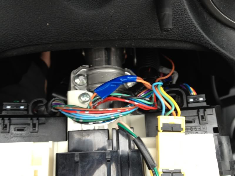
Above: IGNITION SWITCH, (BROWN, 7- Pin Plug) and the Green [Data (in Ignition Databus)] @ front of Key Cylinder Green 7 pin Conn
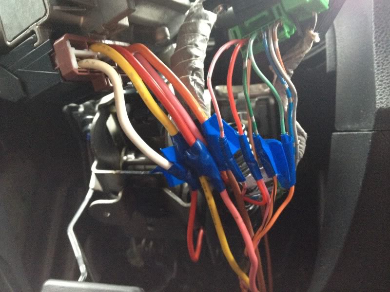
Above: Connection from BROWN Horn Output to HORN / ORANGE (-) @ / HORN SWITCH, (WHITE, 20-Pin Plug) Pin 1
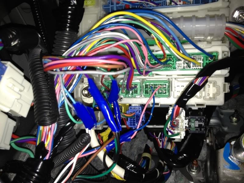
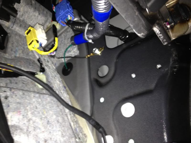
Above: Dash fusebox Lt Green 12 pin Conn; DASH FUSE BOX, (GREEN/WHITE, 49-Pin Plug); DASH FUSE BOX, (LT.GREEN, 8- Pin Plug)
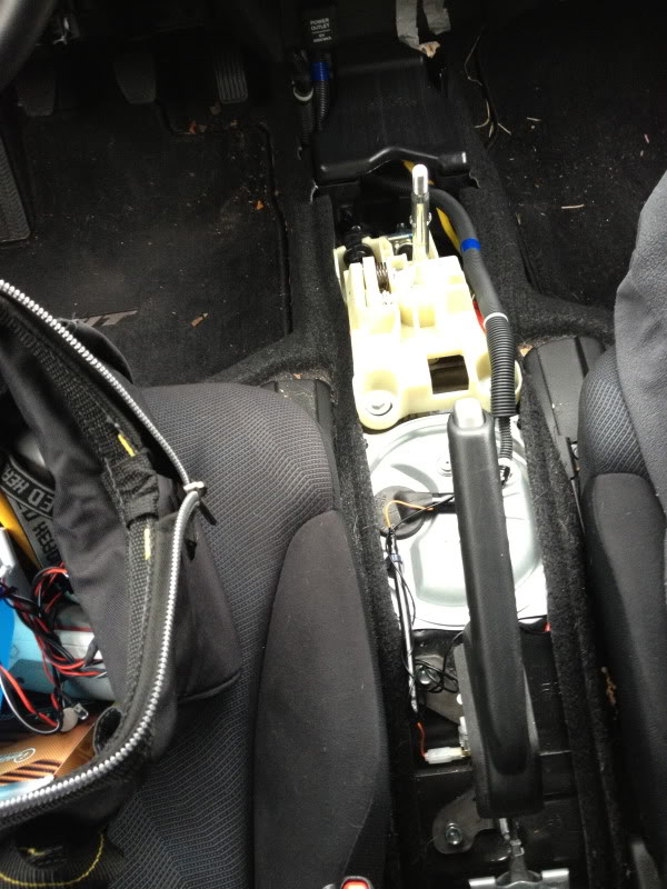
Above: Stick shift with neutral safety wired and E brake wiring
Above: The magnetic reed switch, housed in a piece of fiberglass, with the rare earth magnetic superglued (and magnetized) to the shifter. This connects to the neutral safety switch which goes to ground when the circuit's closed (in neutral).
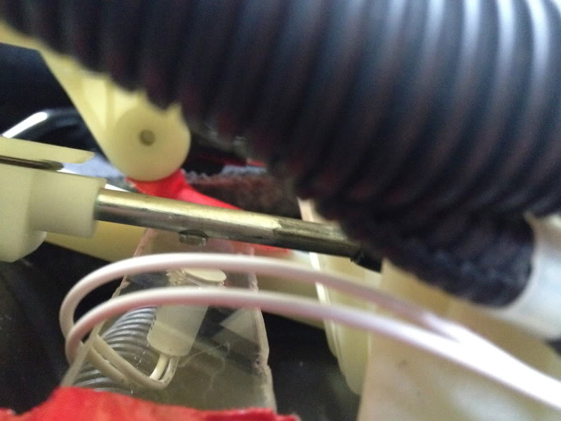
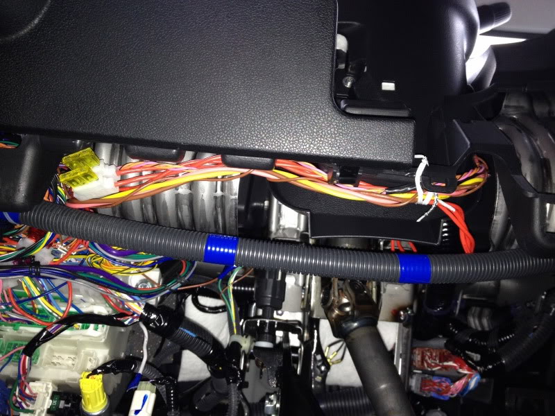
Above: The wire loom with blue electrical tape I installed. It connects my VIOLET/WHITE [Tach Input] (through hole in firewall of passenger’s side) to the LT BLUE Tach Wire
Above: Shows the hole I found in the firewall and ran the Tach input to LT Blue Tach Wire in the engine.
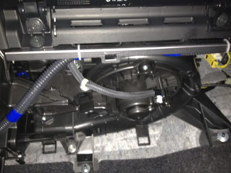
Above: I secured it in a wire loom under the dash here on the passenger's side.
Above: Wire loom under driver's side dash housing neutral safety switch wire and Engine Tach input
Since it's been pretty dead on this thread, I'll post some pictures to hopefully stimulate some thought and interest.
Above: IGNITION SWITCH, (BROWN, 7- Pin Plug) and the Green [Data (in Ignition Databus)] @ front of Key Cylinder Green 7 pin Conn
Above: Connection from BROWN Horn Output to HORN / ORANGE (-) @ / HORN SWITCH, (WHITE, 20-Pin Plug) Pin 1
Above: Dash fusebox Lt Green 12 pin Conn; DASH FUSE BOX, (GREEN/WHITE, 49-Pin Plug); DASH FUSE BOX, (LT.GREEN, 8- Pin Plug)
Above: Stick shift with neutral safety wired and E brake wiring
Above: The magnetic reed switch, housed in a piece of fiberglass, with the rare earth magnetic superglued (and magnetized) to the shifter. This connects to the neutral safety switch which goes to ground when the circuit's closed (in neutral).
Above: The wire loom with blue electrical tape I installed. It connects my VIOLET/WHITE [Tach Input] (through hole in firewall of passenger’s side) to the LT BLUE Tach Wire
Above: Shows the hole I found in the firewall and ran the Tach input to LT Blue Tach Wire in the engine.
Above: I secured it in a wire loom under the dash here on the passenger's side.
Above: Wire loom under driver's side dash housing neutral safety switch wire and Engine Tach input
Last edited by rockoutguy; Apr 1, 2012 at 04:16 PM.
Thread Starter
|
New Member
Joined: Mar 2012
Posts: 7
From: 19047
Update: I confirmed the Omega bypass and Bulldog remote starter turn on and receive power. When I put the key in the ignition to the program the bypass I occasionally get the flashing key indicator on my dash (meaning unrecognized key) and the car won't start. Sometimes the indicator light doesn't come on when placing the key in the ignition and turning to ON, and the car will start fine. The bypass LED stays solid green after pulling the key out of the ignition.
The remote starter makes noise when I hit unlock or lock and will show "armed" when lock is pressed, but the doors don't lock or unlock. When lock is pressed twice, the horn chirps 3 times. The lock and unlock buttons only work after pulling the key out of the igniton and don't do anything after like 30 seconds from pulling the key out of the ignition.
The remote starter makes noise when I hit unlock or lock and will show "armed" when lock is pressed, but the doors don't lock or unlock. When lock is pressed twice, the horn chirps 3 times. The lock and unlock buttons only work after pulling the key out of the igniton and don't do anything after like 30 seconds from pulling the key out of the ignition.

Member

Joined: May 2007
Posts: 22
From: Canada
Hi,
I have a GD3 with a Compustar remote start and alarm. From what I remember the person that installed i said the honda has to pulse the door locks twice to open or close them. most vehicles only need a single pulse to open the locks.
Maybe you need to contact the company you bought the the equipment from for some advise on trouble shooting.
This site has a lot of useful information and people you can ask-http://www.the12volt.com
If not in the GD section of this forum there are a few installers that are pretty active assisting people.
Hope this helps,
Chris
Thread Starter
|
New Member
Joined: Mar 2012
Posts: 7
From: 19047
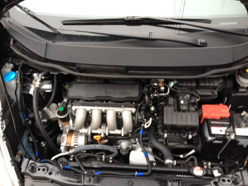
Hey Chris thanks for the only reply so far here. I did post on the12volt and got alot of answers. Ill copy that info over here onto fit freak once I have everything working smoothly. The install has been going well although I've had some issues with the tach learning. I attached my tach input to a light blue wire in a wore loom to the drivers side of the engine and fuel injectors. Bulldog says any brown, red, yellow or blue wire will work for the tach, but I found on wiringinstrucions.com they said a light blue tach wire. I tested this wire with my voltmeter on AC current and it showed:
+ 0.4v AC @ 1000 rpm
+ 0.9v AC @ 2000 rpm
+ 1.4v AC @ 3000 rpm
+ 2.0v AC @ 4000 rpm
So that's where my tach connects. I didn't use a diode on that wire. I programmed the tach learning. The remote starter works fine after a recent start, but if I try to remote start it ~ 45 min later or so it cranks for awhile, like 4 seconds. It remote starts but I want they crank time down. If I remote start it right after that, it cranks normally. I wasn't sure if you or anyone had any thoughts about the tach wire. Should I use a different wire? Should I diode it? I will try to contact bulldog or use another bulldog remote starter unit I have. Also what are ur thoughts on the compustar if I should upgrade? Pros, cons. Etc. and how's the range around buildings or in the city?
Member
Joined: May 2007
Posts: 22
From: Canada
Hi,
The brain I have is the Computar 3000. It has a thousand foot range. It is also a two way paging alarm. I believe my tach wire is brown and it is definitely connected under the hood not under the dash or instrument cluster. Looks to be in the same location your wire is attached to, even though you have GE.
I like the alarm just fine. Command start work from within my work with no problem. Mine does have a turbo timer, shock alarm and passive arming. Doesn't have the automatic cold temperature start and a few of the other features but it works well.
Sounds like you have a great system that just needs a few tweaks to get it working the way you want it to.
Hope someone with more knowledge can point you in the right direction.
Great pictures by the way.
Chris

Thread
Thread Starter
Forum
Replies
Last Post
guitrldy
2nd Generation (GE 08-13)
0
Aug 17, 2011 02:45 PM
dealspecialist
General Fit Modifications Discussion
52
Aug 18, 2010 08:08 AM
flyellow
1st Generation (GD 01-08)
17
Nov 24, 2009 05:36 AM
geepondy
General Fit Talk
0
Oct 24, 2008 11:04 PM