When you click on links to various merchants on this site and make a purchase, this can result in this site earning a commission. Affiliate programs and affiliations include, but are not limited to, the eBay Partner Network.
I promise I am not arguing for the sake of arguing. I love the idea of small bolt on parts that make me think I gained a tiny little bit over the lady filling up her regular fit with groceries and flowers. LOL. Honestly, my comments are still conversational and hopeful to make us all think a step further. I have exhausted my brain power and simply hit the submit button. I hope I correctly shared what I wanted to share.
Originally Posted by evilchargerfan
I'm ready to start a "go fund me page" for you, so you can build that gauge and run this test for us. I think I could "T" into and get an idea... ALSO - I think you have had your TB off... Have you ever seen the faintest sign of oil the filter side of the TB? This would help me/us to understand if air ever really flows in the direction towards the filter side of the TB.
When I'm finally ready to install this thing, I'm thinking off going after Part # 8 on your diagram, where that hose feeds air into the intake -> pre throttle body..... thoughts? Huge if.... If you were putting this on, that would be the one zone to try it in... I agree.
If the product maker has any merit to what they are showing in their JDM diagrams, that t-rev placement should in theory, only allow pressure into/towards the intake, and never backwards towards crank case .... lmk if I sound crazy yall I agree, the Trev would only allow crankcase pressure toward the pipe between the TB and air box. The filter needs to allow fresh air toward the crankcase. The crankcase can pull vacuum while off throttle just the way piston blow-by can cause pressure.
Originally Posted by hotkey
Not quite. This is true during part throttle operation. But at wide open throttle (WOT), zero vacuum in the intake manifold, pcv valve closes, blow-by gases increase and flow reverses. The problem with the images they show is, in my view, they present a re-worked PCV system. This is how the Honda system flows at part throttle: Excellent finding a very accurate drawing of the PCV system. I do disagree about WOT to a small degree. The engine is still sucking, which means unless you have the most amazing air filter ever and a throttle body that can flow at atmospheric pressure at the correct volume, to a small degree, there is vacuum pulling or assisting the positive pressures in the crankcase. From: PCV :: Emissions :: Engine :: Powertrain :: Honda Fit 2007-2019 Repair Manual :: Second generation (2007-2019) - HoFit.org
My theory is, for the T-rev system to work, it probably has a calibrated check valve to create vacuum in the crankcase by regulating the amount of air coming in from the breather at part throttle operation. Then at WOT, the check valve closes and allows blow-by gases to exit via the cheap looking filter. Maybe. First, I completely want to agree that this is their absolute goal. Sadly, based off their drawings, there is air flowing from the crankcase to the air pipe between the throttle body and the filter box. This would happen if there was a HUGE amount of blow-by.
But because the arrows show a different air flow..... Their arrows leave out the fresh air brought in by the mini filter, thus allowing the PCV system to work really well during 99.9% of engine use. Also it does not show the potential for WOT to push oil rich air to the reed valve or out the mini filter. Most of the time the reed valve would be closed or very close to closed (as you say 'regulating") and pulling air through the mini filter due to the needs of the PCV side.
Originally Posted by Pyts
I put like 3 hours into this, mind you im slow as hell, so the mention is to emphasize the effort to respond to all the stuff said. Count another 3 for readin articles.. so heres 110% Huge respect!
i can only assume with the air filter (maybe its explained on the japanese site)...that they intend it to be vacuum relief for the PCV side since it's pulling vaccuum and needs fresh air or blow-by, or both for it to work correctly that is overcome by the reed's pull when throttle is applied and positive pressure in the block is increased. Thatd allow it to maintain a fairly stable amount of negative pressure, assuming they nailed the design. This makes me nervous about filter choice for the knock-offs. It shows this thing essentially supplementing the pcv valve line while also replacing the intake line.
.....................Deleted stuff from original for sake of space.........................
This is... *supposed to be*.. our engine. Correct stop sucking to suck less based on throttle position, or whatever
oh and j's says this thing has no sides top or bottom..? You just make sure airs going the right way.. so you set it up to have sides, so it DOES have sides, just not fixed ones.. the phrasing kinda pisses me off
in regards to the offer to sell a spare, I appreciate it a ton but I'll hold off for now. Once again, car ate all the fun money so theres nothin to pass on. Should be here no later than feb 8.
Originally Posted by hotkey
This is the flow reversal that happens at WOT.
If the T-rev blocks all airflow coming from the airbox, then it makes sense that it would need a way to regulate crankcase vacuum at part throttle. Thus needing a small breather filter.
CyclingFit, when I installed my TB spacer, I did not see any oil residue while in there. I had a rag and cleaner ready, expecting oil..... but found none
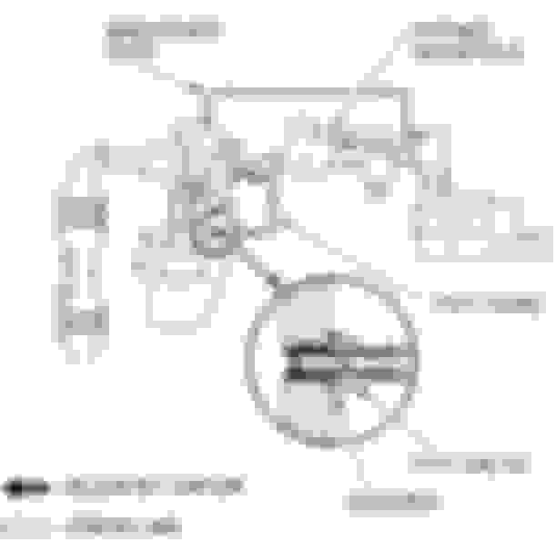
Thanks for the exploded pic! I do wish it was laid out the same way you assembled it, just for my questions sake. Is this part I circled an additional check valve? Is that allowing air to come in through the filter but not escape out of the filter?
Is your intent to have air flow in this direction???? I added the dots as a way to communicate since we are not talking this over in person. I was easier than writing 1, 2, or 3..
It looks like the intent is to have air flow from the (VC) Valve Cover toward the (AI) Air Intake. Then the reed valve closes if the crank case pulls vacuum, thus creating the vacuum that seems to be the goal of this device. My arrow with the single dot would allow air to enter if the vacuum in the crankcase was great enough to pull the sprung check valve open, thus sending air toward the valve cover, which is the same as saying the crankcase. I would imagine air would come through arrow one (single dot) if you quickly went from full throttle to no throttle and the PCV side took a great big suction of air,
I have to admit, my biggest fear is that we actually create a vacuum in the crankcase, which is just as bad as pressure. Remember, pressure is hard to push against, and vacuum is hard to pull away from. They are opposite, but both are equal as far as an issue goes.
Yeah i'll fix the exploded image. Bad case of stupid fingers. If the device functions properly and provides adequate resistance the negative pressure shouldnt be excessive. I recall reading that the desired range is equal or less than -3 psi. Infact i read somewhere that negative pressure is factory in some bmws.
to truly understand this we'll have to dive into some principles of physics. I'm incapable of doing that, so i'm trusting in a higher power.
your drawn direction of flow is correct. Also i tried to show off some holes here, the reed and that check valve. The check valve confuses me, but i went online to verify my assembly.. i guess it opens when the suck isnt on it. Little uncomfortable relying on such a flimsy spring for that, though i do see the necessity
I forgot to add this in. I assume its means for inspection or some kinda drain plug. It could certainly inform you of how much oil is coming to the valve
Okay.. I have a rental unit.. LOL. This is in my hand and I have been able to check it out. I think all this has been confirmed in bits and pieces, but here I go.
Flow is as pictured:
Green Arrow to the air intake = Reed valve allowing one way flow toward the intake. This does allow a very low volume of air to back-flow through the reed valve. VERY low volume.
Blue Arrow = Coming from the valve cover (breather). This for sure lets air go toward the intake, all while crankcase pressure holds the spring loaded check valve closed. Meaning it cannot exhale crankcase gases through the filter. Also for emissions sake, if there is pressure in the system it forces bad gasses toward the intake pipe and not venting to atmosphere.
Blue Arrow = Notice I drew it two directional. If the crankcase needs air, or better said, to control the amount of vacuum in the crank case, the valve can inhale through the filter and past the check valve. So imagine there is too much vacuum, the spring closed valve can slide open and let air in. This is entering through the red arrow direction.
Yellow Arrow = This is the part that I or we, maybe didn't understand until now.<<--- (Since I have not seen directions) That filter assembly can thread in and out. As it threads into and toward the check valve, it actually pushes on the face and compresses the spring on the check valve. This additional preload makes it harder to open what I am going to call the relief valve side of the unit.
It will be a short time before I can test this unit. I need to get a cheap boost / vacuum gauge from Amazon before I kick this off.
Fill car with gas for weigh reasons.
Test the factory system and understand vacuum or pressure inside the breather line. I expect small amounts of vacuum and no noticeable pressure.
Test at wide open throttle and see if there is any chance of pressure or signs of flow from the crankcase.
Test 0-60 and 1000 foot, if possible, with the ScanGaugeII
Install the device with my boost/vacuum gauge on the crankcase side of the valve, then repeat tests 1, 2, and 3. During the tests, confirm that vacuum is not excessive.
If vacuum is lower than previous tests, I will thread the filter inward to lower the flow of the check valve and hopefully lower the pressure a little from stock test levels.
Repeat 1 and 3 to see if there are any changes.
There is a fine line that probably has to be walked... During non WOT (wide open throttle) - vacuum on the PCV side will extract bad stuff from the crankcase. Too much vacuum could actually mean more fresh air would allow more rapid flow of clean air into the crankcase and the intake air filter needs the check valve adjusted to let in more air. More like stock.. Lowering the vacuum and increasing the flow.
Then WOT need to make to make sure that crankcase pressure does not rise. Crankcase pulses should exit through this valve, and some through the PCV, the opposite of the pulse, which is a bit of vacuum, should close the reed valve and create the lower pressure that is ready to accept the next blast of blowby..... All happening at 6000rpm... RPM... LOL.
Remember... pressure and vacuum on the backside of the pistons is equally as bad. The real goal is trying to get the crankcase as neutral as possible. I THINK.
Okay... I need to sleep on this stuff. . If I have typos, I'm sure I'll proof this tomorrow and correct them. Thanks!
Last edited by CyclingFit; Feb 7, 2019 at 09:31 AM.
Sounds like yours is different from mine. i didnt notice adjustment for the filter. Or any ritzy branding. Really appreciating the efforts here and if you're willing to run a gauge... guess i will too. Will report back soonish.
Sounds like yours is different from mine. i didnt notice adjustment for the filter. Or any ritzy branding. Really appreciating the efforts here and if you're willing to run a gauge... guess i will too. Will report back soonish.
Hey Pyts - Yours adjusts too. As I have been doing previously, colored arrows are the easiest way to talk about a photo... The red arrow pointing at the nut, that is a lock nut. The blue arrow pointing at the threads, those threads will thread into the device and apply more pressure between the two faces where I drew the small red arrows, thus tightening the check valve like a flow regulator.
If you use your fingers to plug the air intake side, then manually blow into the device, you should notice almost zero air entering. But if you suck air out of the device, it opens that check valve where the small red arrows are located. This lets the crankcase breathe inward. If you notice that it's way to easy to breathe air inward, then you can adjust the threads at the blue arrow inward, then re-apply pressure on the lock nut to keep the adjustment.
Too much vacuum is bad... Imagine a shop-vac.. When it's plugged it has a huge amount of vacuum, but nothing is actually moving into the canister. You need to keep it from being plugged and it will have much less vacuum, and a way higher flow rate, which is the real goal here. The device we are discussing has the goal of eliminating the forward and backward motion of the air as it flows out of the crankcase at WOT.
Decided to add one more tidbit of info for anyone following along.. Imagining crankcase air is a rope and at WOT it needed to leave through the breather side of the engine, the side that has this device installed. The rope movements would look like this on a stock engine.
This is what they hope the movements look like at WOT with the factory system:
This is what they hope the movements look like at WOT with this device installed:
Disclaimer: I cannot read the language in the youtube videos about this thing. I am simply using my engine and mechanical knowledge to decode what they are trying to achieve with this device. I have no expectations that this is a magical device. I see their goal, but I also think their goal is much better executed on a motorcycle where engineers likely don't have as much design freedom because of size constraints. I would like to believe that Honda has designed and optimized the breather, crankcase size and PCV hose sizes to allow adequate flow out of the crankcase, thus creating as little pressure or vacuum inside the crankcase as possible. Why do I believe this? Because it's calculations like this that give the car better fuel economy and less piston ring, cylinder wall, and bearing wear. Generally speaking, less pressure on any part will extend its life.
Thank you for following along.
Last edited by CyclingFit; Feb 8, 2019 at 09:05 PM.
I need to look into how you draw on pictures. Just forgot is all. Always appreciate the barney style explanations, says a lot about a person's comprehension and communication skills. Dont think its unappreciated.
i'll mess with it today after fixing the refrigerator and the plumbing issues going on...
oh! In other news, once bikes roll off of dealer property (i believe this is true is all or most states) you become free from emissions. Lot of folks, myself included, plug the egr. Engine goes to the float bowl of the carb, carb vents straight down just below frame. never been comfortable with having unfiltered air potentially getting back into the carb.. then into the oil. Along with fuel getting into the oil.. a duplicate will likely go on the bike. Wonder if this could handle fuel at all. anyways
Always appreciate the barney style explanations, says a lot about a person's comprehension and communication skills. Dont think its unappreciated.
......
I work Internal Parts Information Support for the largest independent diesel engine manufacturer in the world... I tend write things the way I wish people would talk to me. LOL. I always want one thought at a time packed into one sentence. This way I can digest what I am trying to read. In the case with my posts here, they are long, but still written pretty quickly. I usually hit submit and then proof read a few more times. Any longer post I make will be different 30 minutes after I make it. LOL.
As for this device. I am trying really hard to figure out what the final goal should be. Also I am trying to figure out what I want to do if initial baseline tests don't show a rise in crankcase pressure.
On to part 2. Install. I found some pictures.. and ofcourse looked for myself, checked the manual for exploded. Gon take some thinking. No clearance by the pcv. Looks like dudes are mounting it on the other side of the intake plenum. This is the only pic i found for it where im confident its the GE.
our mounting bracket aint the same as j's. That aside, it'll just take messin around and some extra
possibly pre-formed hose.
Its as if god reached down from heaven to grab me by the scruff and thrust me forward. I didnt want to kink it. Itll be re-routed later when I find a better path. This method seemed the least hilarious. Used some double sided 3m to affix a rubber bushing so it didnt rattle on the airbox
I'd compare this to what I assume a lightened flywheel would be like.
So you are saying the RPM's seem to fall considerably quicker? Would you say it's the same way upon engine acceleration with the clutch in or in neutral? Still anxiously waiting to mess with the one I have. We have been in and out near zero temps and my garage is the same temp as the outdoors... LOL. Plus chores that come with new home ownership. (fun stuff, like installing soft close toilet seats...)


 Their arrows leave out the fresh air brought in by the mini filter, thus allowing the PCV system to work really well during 99.9% of engine use. Also it does not show the potential for WOT to push oil rich air to the reed valve or out the mini filter. Most of the time the reed valve would be closed or very close to closed (as you say 'regulating") and pulling air through the mini filter due to the needs of the PCV side.