When you click on links to various merchants on this site and make a purchase, this can result in this site earning a commission. Affiliate programs and affiliations include, but are not limited to, the eBay Partner Network.
Edit: I f*ckin meant to quote, not edit.
Welcome to the nightmarish t-rev thread..
Heres a pic of what I've got going on now Went with copper. Kinda lame, but I'll solder up the few fittings still undone and paint it. No more flopping around
Can you find any real world people talking about it and whether it works? The principle they're trying to illustrate in the diagram is unclear to me.
I'm not entirely convinced it's a totally fake idea (I'm looking at you, fifty dollar e-turbo) but I'd also like to understand the benefit. Some kind of smoothness? Fuel economy? I would imagine this does very little for actual acceleration.
that I cannot. being that j's racing slapped their logo on it, I'd like to give them the benefit of the doubt and assume.... this could work (do SOMETHING, even if its a tiny something)
some gk5 owners report a "boggy" take off upon 1st gear, I'm hopeful this little device could help smooth out some of that bog.
Can you find any real world people talking about it and whether it works? The principle they're trying to illustrate in the diagram is unclear to me. I'm not entirely convinced it's a totally fake idea (I'm looking at you, fifty dollar e-turbo) but I'd also like to understand the benefit. Some kind of smoothness? Fuel economy? I would imagine this does very little for actual acceleration.
50 buck e turbo!? I'm sold!!!
based on what I've read on the subject this past ten minutes im a touch nervous about the concept, but have confidence in j's, and thus j clones. Significant or not, you'd have to be some kind of devil to anodize a junk mod, hah! I'm just wonderin now if maintaining constant negative pressure in the crankcase would encourage blow-by. I didnt expect to see an ebay one, so I wanna try it too dammit. Pretty happy to see all the interest by the way.
whereas I read that its an issue for engines to get that extra blow by air via intake at higher rpms due to the fact that it can jack up the afr, I imagine our computers are pretty adaptive, so this may have a similar effect to adding an aftermarket intake without having to ditch your effective paper filter for a foamy mesh that dont protect your engine as good, not to mention their theory about reducing resistance against the pistons dropping down... but would that be added to the pistons going up? Maybe up aint as big a deal since the down stroke is more aggressive?
other concern would be potential for oil to get sucked into the intake, so again the amount of negative pressure generated would have to be juuust right eh?
to me this is still a worth-while gamble. J's raced the GE with it, some wide wheels (stock offset), their spoiler and 1.5 way helical lsd and apparently had some success. Thems some relatively minor mods
Wanted to update with a forum link that covers the topic pretty extensively: A pretty good read
Key points that I found:
� gettin rid of positive pressure am good
� adding oil catch can is a consideration, depends on how the t-rev handles the oil
� ambient air vent for valve cover *may* help eliminate risk of excessive & unnecessary suck.
the more i dig up, the more interesting this concept is. Found other forum stating that negative case pressure is stock standard with a number of beemers.
as is, alot of members are already collecting a crap ton in their catch cans. do you think this t-rev system .... would result in even MORE oil, being collected?
as is, alot of members are already collecting a crap ton in their catch cans. do you think this t-rev system .... would result in even MORE oil, being collected?
Absolutely, but they shouldnt be passing a significant amount of oil unless something is wrong with the engine. Thatd be a huge design flaw otherwise. Honestly I'd like to know more about the engines that are losing so much oil.
the question here is how much neg pressure we're talking. I'll do some reading, some folks already pulled the trigger and I'm sure we'll hear from them
Item is inbound, should be here early february. I went with the 120 buck one from canada. Filter looked better, and it should actually get delivered.. mentioned the forum and made an offer for 100 bucks, they accepted within an hour. Not sure how far you can lowball em, theres no way they're moving a lot of those, especially with the chinese counterpart being so cheap.
will update as soon as shes installed! Here's hoping.
Update on the thermal electric motor: theres no update. Cant rely on family. Still, the company makin em is pretty fancy. I'll keep nagging whether theres any interest or not. If the chingas performs
it'll be a big deal.
I see this is about the GE, and I don't have a GE so I am a little out of my knowledge base. I'll give this thought in reference to a GK. Again, this is very much about the GK engine because I don't know how the PCV system works on the GE cars. I may research though...
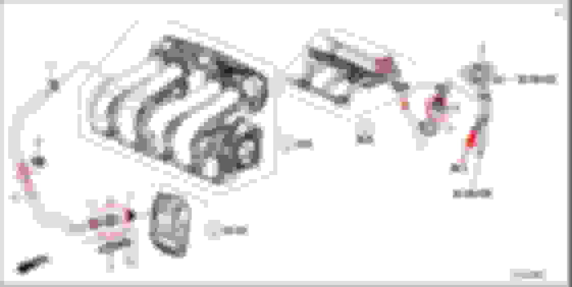
This is basically a PCV valve for the crankcase fresh air induction side. This is on the backside of the Earth Dreams engines. Not the area where we install oil catch can systems into the PCV tract. Notice in their drawings they have the valve feeding to the filter side side of the throttle body.
Notice they do not put this on the PCV side of the crankcase because the inlet filter on the device would create a vacuum leak of non-metered air. In a GK car there is a pipe on the atmosphere / filter side of the throttle body and the PCV system is drawing from the intake side of the throttle body to introduce clean air into the crankcase and allow the vacuum or PCV side to more easily suck the bad stuff from the crankcase.. If the Earth Dreams did not have fresh air being introduced, it would count only on positive pressured created by the combustion process and engine blow-by. I would venture to say that the earth dreams is near ZERO pressure in the crank case. If it ever had positive pressure, I think we would see signs of oil on the filter side of the throttle body.
If installed on the crankcase clean air side, you would want clean air to flow toward the crankcase and no dirty air to flow toward the throttle body.
Because our engines are naturally aspirated, they are sucking air all the time on the PCV side. As long as the PCV side is working correctly and is unblocked, you should never see anything oily making it through the pipe that attaches the crankcase to the inlet side of the intake tract on the filter side of the throttle body.
IF this is installed in the PCV tract and air can pull through that filter, you will get clean air into the intake, but you will also lose the vacuum that pulls the bad stuff from the crankcase.
I am most bugged out by the filter that is installed in the pics. A reed valve and a ball check valve are basically the same thing. I understand trying to only allow air to flow in one direction but I do not understand the need to introduce air through the filter and into the system.
I would love to discuss this further if anyone wants to put on their technical caps... And I may have missed something very obvious.
My chinese clone came in. I'd love to test it, but my gk5 is down for a bit
Pyts, if you cant wait for yours to arrive ... PM me. I did purchase a spare / own 2
CyclingFit , I too am a little bothered with the breather. There appears to be 2 ways to do the filter location, what are your thoughts on the following 2 pictures?
And, if you were to install it.... how would you set it up?
I just cannot picture the value of the filter or really the entire thing. If I built a race engine, it would look cool and be used in place of a pcv valve. But also I would not push any PCV into a race engine and I would change the oil more often. Also, when I see it the T-rev used in photo's by T-rev, I am not seeing the filter. (I haven't looked too hard) It isn't until J's gets hold of it that I see the filter get added to many pictures.
To put this on the PCV side would not do anything. Part labeled "4" is a check valve and all this device is, is a different type of check valve. Introducing a second check valve to the system would only hinder the engines ability to use vacuum to pull the "bad stuff" from the crankcase.
On part "5" I drew and arrow to explain the direction the air is being pulled by vacuum. Yes, to a point there is also POSITIVE crank case ventilation too, but it has to be minimal. Why is it minimal? Because part "6" is attached to the intake pipe, BEFORE the throttle body. This mean that it always has atmospheric pressure willing to help the air travel into the valve cover area. This will then allow a smooth flow of air down the oil return passages and give this clean air to the crankcase. .............. Now back to part numbers "4" and "5" .... They are pulling vacuum because they are connected to the intake manifold and most importantly, the air and bad stuff the flows in is located between the intake valves and the throttle body. This is the area that has less than atmospheric pressure because the engine is sucking in air and the throttle body is trying to prevent air from getting in. This is what creates vacuum.
So here is the tough part for me... I have no idea where I would install this thing. If I was forced to put it on my car, I would remove the PCV valve and install the proper fitting that was a full flow fitting and had no ball check. I would then install this between the crank case and the intake manifold and I would do so without the filter. I would plug the filter hole because I can only see that as removing vacuum, which is what is doing almost all of the work to get crap out of the crankcase.
Sorry, I can't wrap my mind around this. I am trying really hard or I wouldn't have given it an hour and a half of my day. I am still happy to keep discussing.
Side note: If someone has a cheap vacuum gauge or better yet a boost gauge sitting around, they could T it into the fresh air introduction side and see if it ever pulls vacuum, this means the pistons are having a hard time going upward (which I highly doubt because you have just as much piston going up as you do coming down, so the volume of the crankcase isn't changing too much). Then the exact opposite could be said, if the boost gauge goes upward, then your blow-by past the pistons and the movement of the pistons is creating pressure in the crankcase, this would also mean the PCV valve, hose, and vacuum from the intake would not be doing a good enough job to manage the crankcase pressures.
I may make a youtube video.. LOL
Last edited by CyclingFit; Jan 30, 2019 at 05:03 PM.
I'm ready to start a "go fund me page" for you, so you can build that gauge and run this test for us.
I'm even willing to lend my t-rev (since my car is down for a month) for you to run said tests on.
When I'm finally ready to install this thing, I'm thinking off going after Part # 8 on your diagram, where that hose feeds air into the intake -> pre throttle body..... thoughts?
If the product maker has any merit to what they are showing in their JDM diagrams, that t-rev placement should in theory, only allow pressure into/towards the intake, and never backwards towards crank case .... lmk if I sound crazy yall
My theory is, for the T-rev system to work, it probably has a calibrated check valve to create vacuum in the crankcase by regulating the amount of air coming in from the breather at part throttle operation. Then at WOT, the check valve closes and allows blow-by gases to exit via the cheap looking filter. Maybe.
But because the arrows show a different air flow.....
I put like 3 hours into this, mind you im slow as hell, so the mention is to emphasize the effort to respond to all the stuff said. Count another 3 for readin articles.. so heres 110%
i can only assume with the air filter (maybe its explained on the japanese site)...that they intend it to be vacuum relief that is overcome by the reed's pull when throttle is applied and positive pressure in the block is increased. Thatd allow it to maintain a fairly stable amount of negative pressure, assuming they nailed the design. This makes me nervous about filter choice for the knock-offs. It shows this thing essentially supplementing the pcv valve line while also replacing the intake line.
They enphasize that they do installation.. surprise. If nothin else they made a badass headache device.
heres pics n some crap I drew poorly cuz I'm my father's son.
My 91 chevy cuz i see the engine bay in my nightmares This is... *supposed to be*.. our engine. Correct stop sucking to suck less based on throttle position, or whatever
heres my primary source:
https://www.onallcylinders.com/2017/05/05/ask-away-jeff-smith-choose-build-pcv-system-control-oil-vapor/
oh and j's says this thing has no sides top or bottom..? You just make sure airs going the right way.. so you set it up to have sides, so it DOES have sides, just not fixed ones.. the phrasing kinda pisses me off
in regards to the offer to sell a spare, I appreciate it a ton but I'll hold off for now. Once again, car ate all the fun money so theres nothin to pass on. Should be here no later than feb 8.
Forgot to mention its supposed to prevent oil in the intake by "preventing emulsification" through design.
cant tell if thats a vapor separator of some kind or theyre just sayin the reed does somethin wacky and the housing is rifled so that... keeps oil from comin out, eliminating need for a catch can which should otherwise be installed between a pcv and valve cover.
if you opt for the catch can route get a fitting and switch to an inline pcv. Vague, right?
This is... *supposed to be*.. our engine. Correct stop sucking to suck less based on throttle position, or whatever
This is the flow reversal that happens at WOT.
If the T-rev blocks all airflow coming from the airbox, then it makes sense that it would need a way to regulate crankcase vacuum at part throttle. Thus needing a small breather filter.


 im a touch nervous about the concept, but have confidence in j's, and thus j clones. Significant or not, you'd have to be some kind of devil to anodize a junk mod, hah! I'm just wonderin now if maintaining constant negative pressure in the crankcase would encourage blow-by. I didnt expect to see an ebay one, so I wanna try it too dammit. Pretty happy to see all the interest by the way.