
Radio Harness Pin Layout


Thread Starter
|
Member
Joined: Jan 2014
Posts: 273
From: City of Angels

Radio Harness Pin Layout
Ok.. removed the original post and here is the result from what I have found:
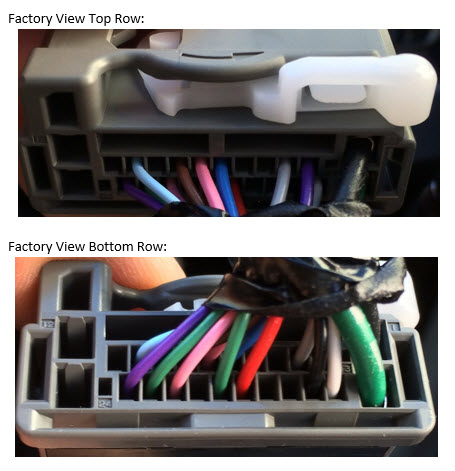
1) Factory layout looking from the rear view where the wires/pins enter into the harness:
2) Mapped out Pins so far
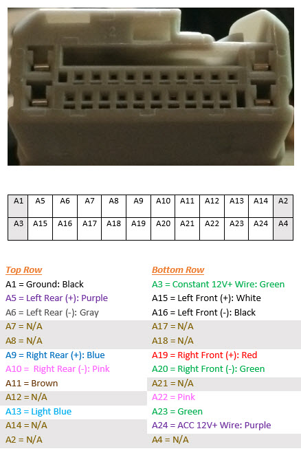
As for why the off on labeling for A1-A4. It is to match this: FIT Infotainment and HVAC Wiring Diagrams
1) Factory layout looking from the rear view where the wires/pins enter into the harness:
2) Mapped out Pins so far
As for why the off on labeling for A1-A4. It is to match this: FIT Infotainment and HVAC Wiring Diagrams
Last edited by fibrepunk; Feb 18, 2015 at 01:50 AM. Reason: got the pin layout - for audio with pictures
Member
Joined: Oct 2009
Posts: 4,295
From: Wandering around.
The following info is for the SECOND gen Fit... so, doubt it applies to the 3rd gen. I'm just gonna leave it here in case anyone stumbles upon it and wants it.
Unless you plan on making a harness adapter from scratch, the Metra/Scosche (and any other brand out there) adapters are already pin matched.
But if you must know... your numbers are slightly off from the actual pin numbers, they put 1-12 on top and 13-24 on bottom (top, being where the clip/hook is). In the service manual, it's called the "Audio unit connector A (24P)," hence the A's you'll see. I'll use "---" for empty pins.
A1 : RED - dash lights brightness controller (ILL-)
A2 : ---
A3 : BLU - Data link connector (K-line)... diagnostics?
A4 : GRN - Security control
A5 : --- for non-navi, for navi WHT audio remote GND ***
A6 : ORN - RR R-
A7 : BLU - RR R+ (hum, blu again?)
A8 : ---
A9 : ---
A10 : BRN - RR L-
A11 : GRY - RR L+
A12 : BLK - Ground
A13 : GRY - #29 fuse in under-dash panel (ILL+)
A14 : ORN - #14 fuse (ACC)
A15 : BLU - ECM/PCM Vehicle Speed Pulse
A16 : --- for non-navi, for navi PNK audio remote ***
A17 : ---
A18 : RED - FR R-
A19 : BRN - FR R+
A20 : ---
A21 : ---
A22 : LT GRN - FR L-
A23 : LT BLU - FR L+
A24 : PNK #1 fuse (+B)
Ain't it awesome that they reuse multiple color wires... even used blue 3 times!
As for pins #5 & #16, you can add the steering controls for non-navi by adding the control and running wires there.
Urgh... couldn't copy/paste, since this is from the physical copy of the service manual. =.="
Last edited by Goobers; Feb 2, 2015 at 05:45 PM.
Thread Starter
|
Member
Joined: Jan 2014
Posts: 273
From: City of Angels
Thanks for the 2nd gen pin layout. Looking for 3rd gen here and knowing the pin layout will all people who don't want to splice into the wire to connect the Metra 71-1729 & Metra 70-1729 first and which wires to use for the AMP before pulling out the HU. Simply just plug in after pulling out the HU if the pin layout is known.
Damn, that's what I get for not checking which sub-forum this came from... I saw the topic from the main forum page.
The following info is for the SECOND gen Fit... so, doubt it applies to the 3rd gen. I'm just gonna leave it here in case anyone stumbles upon it and wants it.
Unless you plan on making a harness adapter from scratch, the Metra/Scosche (and any other brand out there) adapters are already pin matched.
But if you must know... your numbers are slightly off from the actual pin numbers, they put 1-12 on top and 13-24 on bottom (top, being where the clip/hook is). In the service manual, it's called the "Audio unit connector A (24P)," hence the A's you'll see. I'll use "---" for empty pins.
A1 : RED - dash lights brightness controller (ILL-)
A2 : ---
A3 : BLU - Data link connector (K-line)... diagnostics?
A4 : GRN - Security control
A5 : --- for non-navi, for navi WHT audio remote GND ***
A6 : ORN - RR R-
A7 : BLU - RR R+ (hum, blu again?)
A8 : ---
A9 : ---
A10 : BRN - RR L-
A11 : GRY - RR L+
A12 : BLK - Ground
A13 : GRY - #29 fuse in under-dash panel (ILL+)
A14 : ORN - #14 fuse (ACC)
A15 : BLU - ECM/PCM Vehicle Speed Pulse
A16 : --- for non-navi, for navi PNK audio remote ***
A17 : ---
A18 : RED - FR R-
A19 : BRN - FR R+
A20 : ---
A21 : ---
A22 : LT GRN - FR L-
A23 : LT BLU - FR L+
A24 : PNK #1 fuse (+B)
Ain't it awesome that they reuse multiple color wires... even used blue 3 times!
As for pins #5 & #16, you can add the steering controls for non-navi by adding the control and running wires there.
Urgh... couldn't copy/paste, since this is from the physical copy of the service manual. =.="
Member
Joined: Oct 2009
Posts: 4,295
From: Wandering around.
Thanks for the 2nd gen pin layout. Looking for 3rd gen here and knowing the pin layout will all people who don't want to splice into the wire to connect the Metra 71-1729 & Metra 70-1729 first and which wires to use for the AMP before pulling out the HU. Simply just plug in after pulling out the HU if the pin layout is known.
But I dunno... somehow, that doesn't seem right.
edit: http://a248.e.akamai.net/pix.crutchf.../120701729.PDF indicates that the amp wire on the Metra harnesses would be pin A17, but for the 2nd Gen Fit, there's nothing there from the stock radio (no amp to power). The pinout (for 70-1729), thus requires an aftermarket radio that provides amp pwr. I haven't seen any mention of the GK having amps from the factory, so I'd say it doesn't have anything there either.
Last edited by Goobers; Feb 4, 2015 at 12:10 AM.
Thread Starter
|
Member
Joined: Jan 2014
Posts: 273
From: City of Angels
That's odd, supposedly using the same connector for the 2nd Gen... if that's the case, then the pinout would be the same.
But I dunno... somehow, that doesn't seem right.
edit: http://a248.e.akamai.net/pix.crutchf.../120701729.PDF indicates that the amp wire on the Metra harnesses would be pin A17, but for the 2nd Gen Fit, there's nothing there from the stock radio (no amp to power). The pinout (for 70-1729), thus requires an aftermarket radio that provides amp pwr. I haven't seen any mention of the GK having amps from the factory, so I'd say it doesn't have anything there either.
It looks like the arrangement of the pins are not the same for 2nd and 3rd Gens on the harness. Here is the wiring diagram for the GK.
Member
Joined: Oct 2009
Posts: 4,295
From: Wandering around.
That is strange... I wonder why Crutchfield (and other places) say the Metra 70/71-1729 is compatible, without mentioning that the pins need moving to make it actually work. Metra will need to release a new part number for 2015 Fit with the different arrangement(or populate more pins to keep it "2008-up").

Member
Joined: Jul 2014
Posts: 85
From: Michigan
I need to the know the function of A11, A13, A22 & A23....besides the color. I noticed on the diagram light blue (a-13) is linked to front accessory power socket relay and keyless access control unit, but the other three? What would happen if I don't do anything to the missing pins to an aftermarket stereo?
Member
Joined: Aug 2014
Posts: 1,620
From: Connecticut
I need to the know the function of A11, A13, A22 & A23....besides the color. I noticed on the diagram light blue (a-13) is linked to front accessory power socket relay and keyless access control unit, but the other three? What would happen if I don't do anything to the missing pins to an aftermarket stereo?
A13 - K Line (Detects Scan Tool Signal)
A22 - Audio Remote Switch (Detects signal from audio remote switch)
A23 - Display Switch (Detects signal from audio remote switch)
FYI, the pins above are for the GK 3rd gen.
Last edited by Bassguitarist1985; Aug 31, 2015 at 10:50 AM.

Member
Joined: Jul 2016
Posts: 65
From: longueuil, quebec, canada
is somebody can told me what is the dash illumination light color cable or pin number on the gk fit model ? i try to figure how to plug my alpine , i order the metra 70-1729 , now for the 4 speakers , ground , yellow , red and , blue it seems ok but i have the orange for the illumination dash , i plan to change my lx radio , it was much more simple in my corolla 
Last edited by fred9000; Sep 12, 2016 at 06:03 PM.

Member
Joined: Aug 2014
Posts: 1,620
From: Connecticut
Check out my audio thread, It has the info there. I dont know if the MXDM is the same radio pinout as the USDM Fits, but for the USDM 2015-2017, it would be A24, which is the ACC power. You need to use this pin for the remote turn on. A22 is for the steering wheel controls, that would not work.
Now if you have a 2018+ Fit, there is a completely different pinout configuration with different plug shape used on the Civics that you will need to follow. All info is on my build thread.
Last edited by Bassguitarist1985; Aug 5, 2019 at 02:13 PM.

New Member
Joined: Aug 2019
Posts: 3
From: Guadalajara
Check out my audio thread, It has the info there. I dont know if the MXDM is the same radio pinout as the USDM Fits, but for the USDM 2015-2017, it would be A24, which is the ACC power. You need to use this pin for the remote turn on. A22 is for the steering wheel controls, that would not work.
Now if you have a 2018+ Fit, there is a completely different pinout configuration with different plug shape used on the Civics that you will need to follow. All info is on my build thread.
Now if you have a 2018+ Fit, there is a completely different pinout configuration with different plug shape used on the Civics that you will need to follow. All info is on my build thread.
Many thanks for your recomendation this weekend l�ll try!

@fred9000 do you have xp with alpine stereos? Would you recommend them?
Sorry for being off topic.
I'm looking for a good stereo and my vote will be on the Alpine.
Now I was trying to gather as much info as possible but most review blogs are junk.
I mean they are hyping and when I've checked out some actual customer reviews the
difference is huge.
Along with my journey in review land I came across a different site. It seems to be the real deal. I mean it harshly criticizes the flaws that each brand has. This has put me on the fence.For example there's a review about Alpine w650 radio unit. I was eyeing this headunit.
How bad is that slow startup? Does it take 20s to boot up? What about the value for the money?
Any insights are highly appreciated

New Member
Joined: Jan 2020
Posts: 2
From: Port Neches, Texas
2013 Honda Fit sport hatchback. Does anyone know which wires are used on the vehicle audio harness to hook up the steering wheel control from my after market radio? The wires on my aftermarket radio are as follows. Brown: Key 1+ and Brown/Black: Key 2-

New Member
Joined: Mar 2022
Posts: 1
From: Tijuana
Has anybody updated this info? I just found out via the ASWC-1 that you have to connect A11 to chassis ground pin to enable A22 and A23 resistor ladder (Steering Wheel Control, aka SWC), which can be picked up by any aftermarket radio.
Last edited by pilgrim; Mar 8, 2022 at 11:49 PM. Reason: SEO friendly term

Thread
Thread Starter
Forum
Replies
Last Post
john dna
General Fit Talk
2
Jan 30, 2023 08:06 AM
im the fit
Fit Engine Modifications, Motor Swaps, ECU Tuning
9
May 3, 2009 12:07 AM