
DIY: Independent Fog w/ Original Switch.


Nice! But one question. Is that the right size add-a-circuit? Looks a little big from the pic. Make sure b4 you start the project that you take it out of the package and try it to see if it fits in your fuse slots.

I just finished the fog light mod and works perfectly!!
only things i would add as heads up for those attempting
1) i would personally use 14 or 16 gauge wire. I used 12 gauge which worked fine, it was just a little large and stiff. I think the fog light wire is 16 gauge.
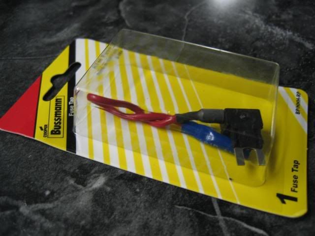
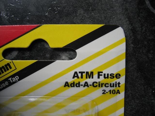
2) When purchasing the ADD-A-Circuit make sure it says ATM or Mini on the package.
3) As sick fit said putting the two fuses in the add a circuit, its a tight fit, using a pair of vice grips (gently) makes it easier.
Other than that great write up and a fun mod to do
only things i would add as heads up for those attempting
1) i would personally use 14 or 16 gauge wire. I used 12 gauge which worked fine, it was just a little large and stiff. I think the fog light wire is 16 gauge.
2) When purchasing the ADD-A-Circuit make sure it says ATM or Mini on the package.
3) As sick fit said putting the two fuses in the add a circuit, its a tight fit, using a pair of vice grips (gently) makes it easier.
Other than that great write up and a fun mod to do
I just finished the fog light mod and works perfectly!!
only things i would add as heads up for those attempting
1) i would personally use 14 or 16 gauge wire. I used 12 gauge which worked fine, it was just a little large and stiff. I think the fog light wire is 16 gauge.
2) When purchasing the ADD-A-Circuit make sure it says ATM or Mini on the package.
3) As sick fit said putting the two fuses in the add a circuit, its a tight fit, using a pair of vice grips (gently) makes it easier.
Other than that great write up and a fun mod to do

Member
Joined: Feb 2008
Posts: 84
From: ontario
WAIT A MINUTE!!!!!!!!!
WARNING!!!!!!!!!!!
sick fit wrote "yellow/red" wire which means "yellow wire with red stripe"
what he meant was "red/yellow" wire which means "red wire with yellow stripe"
red/yellow and yellow/red are NOT the same thing!!!!!!
PLEASE BE CARE to all the posters
WARNING!!!!!!!!!!!
sick fit wrote "yellow/red" wire which means "yellow wire with red stripe"
what he meant was "red/yellow" wire which means "red wire with yellow stripe"
red/yellow and yellow/red are NOT the same thing!!!!!!
PLEASE BE CARE to all the posters
Before I begin, I know there is question about this working with high beam or not. But this is not to work in conjunction with highbeams.
There are more steps for that and I do not know them. This is just for those FitFreak members that want Independent Fogs.
Disclaimer: The following is provided as a GUIDE ONLY, and neither myself, nor FITFREAK.NET endorse, recommend, encourage nor take any responsibility for the outcome of someone else doing the following. You follow these steps at your own risk!
I know you have seen many ways already for setting up an independent fog switch. This info has been gathered from reading all the threads and posts on this topic and of course doing it myself. So thanks to those that figured this out.
I have performed this mini project on 5 local Fits (Including mine) and they ALL HAVE BEEN SUCCESSFUL with NO HIGHBEAM DASH LIGHT ON.
Please follow these easy steps and please do not add on to these instructions, and you will be on your way to Independent Fogs!
Difficulty Level from 1-10: 2
Most Importantly Materials You will need before you begin.
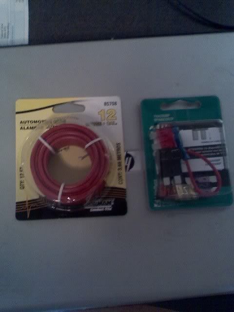
- one 16 - 12 gauge wire about 2 feet legth.
- an "add a circuit" that brings 10amp fuses from your local auto store.
- Cutting plyers.
- Connectors w/ wire crimper or Solder tool
- Electrical tape
________________
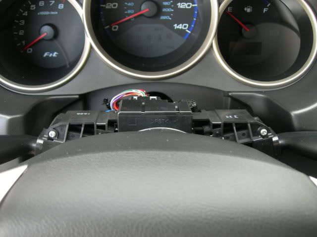
Step 1: Remove the Steering wheel dash cover. A little tug will do.
_________________________
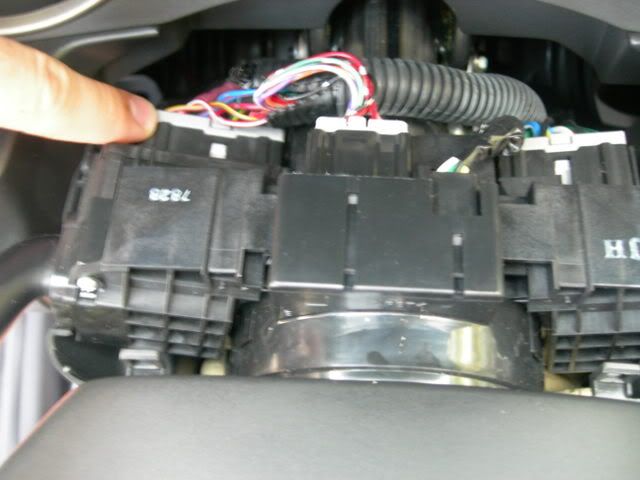
Step 2: There will be three harness that you are facing. Locate the harness to your left. This one... and take it out like so.
_______________________
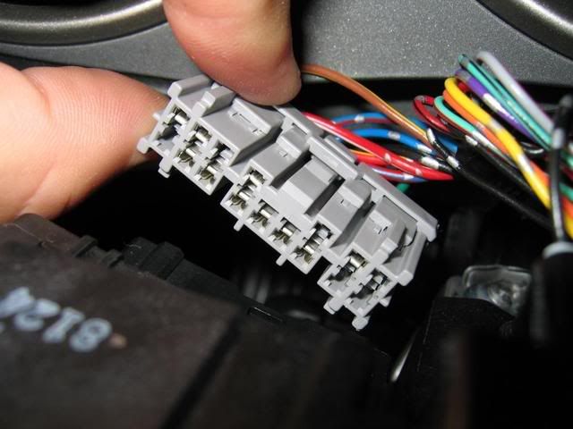
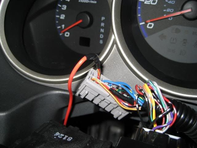
Step 3: Locate the Yellow/Red wire on that harness. And cut it about 1-2 inches from the harness like so.
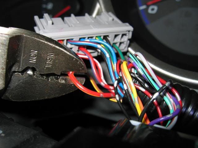
____________________
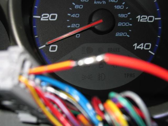
Step 4: In this step you may use either a solder tool like Atticus (Fitfreak Member) did or you may use a simple connector like I did. Also, you may now disregard the loose wire from the bundle and focus on only the Yellow/Red wire that is still on the harness. Go ahead and strip about 1cm of wire to bare copper. And either solder or add a connecter to that end like so with a 2 foot spare wire you bought or have lying around that is about or equal to the same width of the wire that is on the harness.
or
______________________
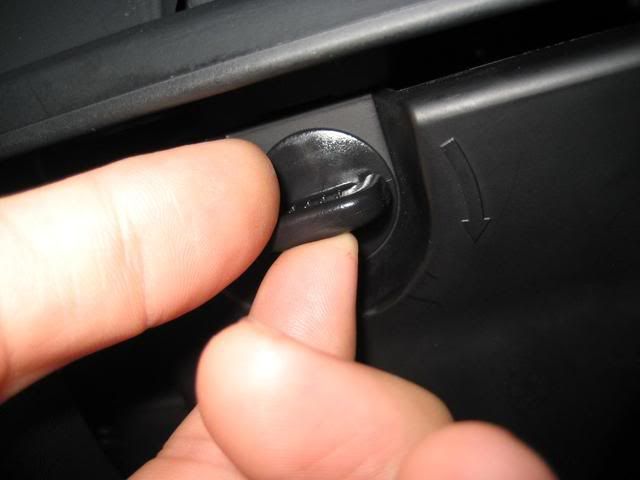
Step 5: Locate the Fuse box door to the bottom left of the steering wheel location like so and unlock and remove the door.
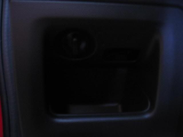
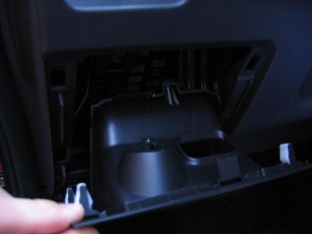
______________________
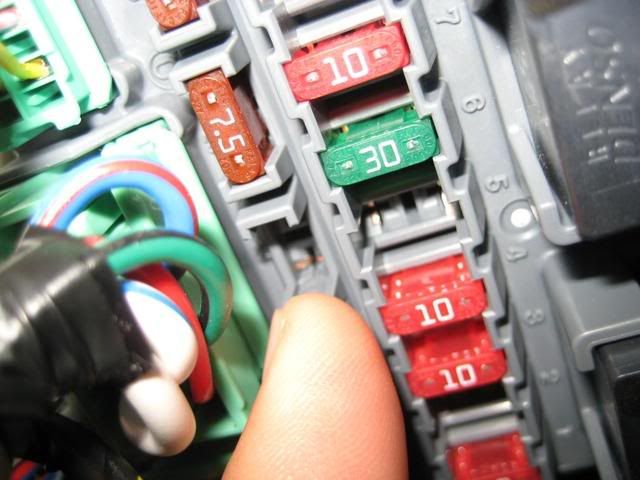
Step 6: When you look inside you will see the fuse box. Go ahead and remove the 10amp fuse from slot #3 with your little white fuse remover which you should have in your fuse box. I know Atticus was not pointing at slot #3 but just look at slot #3 and remove that 10amp fuse and set aside.
___________________
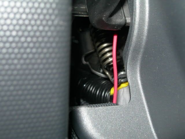
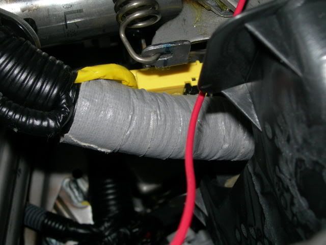
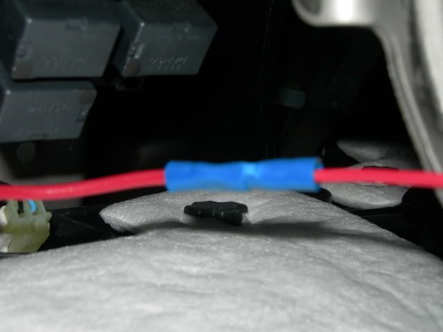
Step 7: Go back up to your steering dash and run the 2 foot long wire (red wire you see) that you connected with the Yellow/Red wire to the back of the steering wheel and you should see the wire go down the back of the steering wheel dash smoothly like so to where you should then see it reach to the fuse box.
_______________
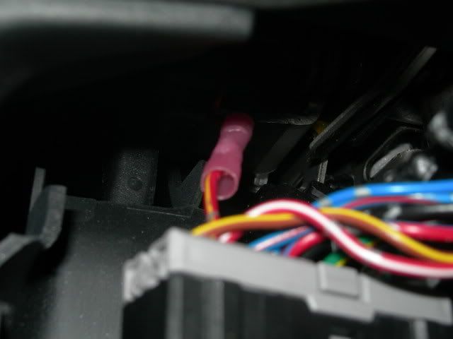
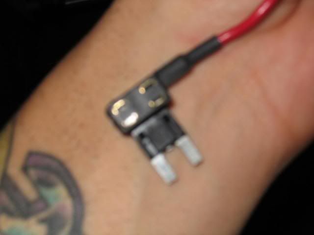
Step 8: Now this is where you use the "add a circuit". Go ahead a cut the 2 foot long wire (that went in back of the steering wheel) to proper length to get rid of excess wire and connect the 2 foot long wire to the "add a circuit" and use the wire crimper like so on the blue connecter that comes with the "add a circuit".
_________________
Step 9: You will notice that the "add a circuit" has two slots as seen in this pic. Go ahead and add the 10amp fuse we set aside earlier into one of the slots and another 10amp fuse to the other slot. It will be a really tight fit for those 10amp fuses to fit in those two slots in the "add a circuit". But believe me, it goes in.
______________________
Step 9: Next, get the "add a circuit" that you have with the two 10 amp fuses and put it in slot #3 of your fuse box like so.
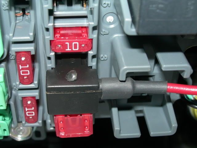
______________
Step 10: Lastly, make sure none of your wires have exposed copper. If so, use electrical tape and put everything back together (close fuse box, plastic steering dash) and the harness back in place.
Oh, if your wondering about the loose Yellow/Red wire that we cut at the beginning that was in a bundle of other wires, you can electrical tape the end and disregard it.
Thanks to Atticus for providing me with most of the pics. The rest were from my setup.
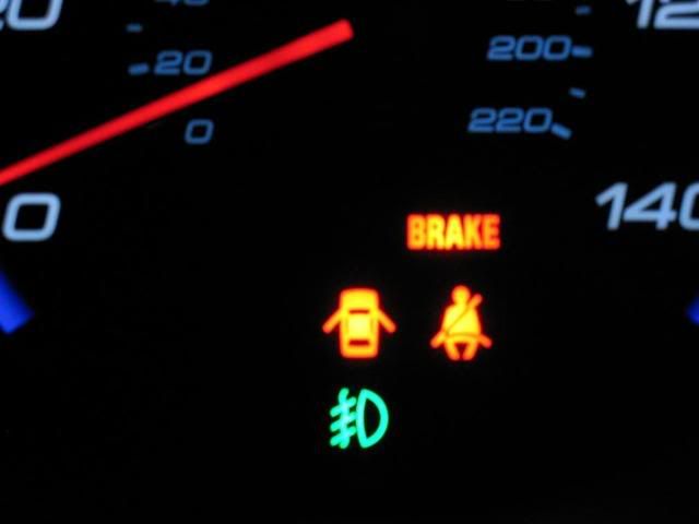
Did you notice??? There was no need to ground. And the best part... this
There are more steps for that and I do not know them. This is just for those FitFreak members that want Independent Fogs.
Disclaimer: The following is provided as a GUIDE ONLY, and neither myself, nor FITFREAK.NET endorse, recommend, encourage nor take any responsibility for the outcome of someone else doing the following. You follow these steps at your own risk!
I know you have seen many ways already for setting up an independent fog switch. This info has been gathered from reading all the threads and posts on this topic and of course doing it myself. So thanks to those that figured this out.
I have performed this mini project on 5 local Fits (Including mine) and they ALL HAVE BEEN SUCCESSFUL with NO HIGHBEAM DASH LIGHT ON.
Please follow these easy steps and please do not add on to these instructions, and you will be on your way to Independent Fogs!
Difficulty Level from 1-10: 2
Most Importantly Materials You will need before you begin.
- one 16 - 12 gauge wire about 2 feet legth.
- an "add a circuit" that brings 10amp fuses from your local auto store.
- Cutting plyers.
- Connectors w/ wire crimper or Solder tool
- Electrical tape
________________
Step 1: Remove the Steering wheel dash cover. A little tug will do.
_________________________
Step 2: There will be three harness that you are facing. Locate the harness to your left. This one... and take it out like so.
_______________________
Step 3: Locate the Yellow/Red wire on that harness. And cut it about 1-2 inches from the harness like so.
____________________
Step 4: In this step you may use either a solder tool like Atticus (Fitfreak Member) did or you may use a simple connector like I did. Also, you may now disregard the loose wire from the bundle and focus on only the Yellow/Red wire that is still on the harness. Go ahead and strip about 1cm of wire to bare copper. And either solder or add a connecter to that end like so with a 2 foot spare wire you bought or have lying around that is about or equal to the same width of the wire that is on the harness.
or
______________________
Step 5: Locate the Fuse box door to the bottom left of the steering wheel location like so and unlock and remove the door.
______________________
Step 6: When you look inside you will see the fuse box. Go ahead and remove the 10amp fuse from slot #3 with your little white fuse remover which you should have in your fuse box. I know Atticus was not pointing at slot #3 but just look at slot #3 and remove that 10amp fuse and set aside.
___________________
Step 7: Go back up to your steering dash and run the 2 foot long wire (red wire you see) that you connected with the Yellow/Red wire to the back of the steering wheel and you should see the wire go down the back of the steering wheel dash smoothly like so to where you should then see it reach to the fuse box.
_______________
Step 8: Now this is where you use the "add a circuit". Go ahead a cut the 2 foot long wire (that went in back of the steering wheel) to proper length to get rid of excess wire and connect the 2 foot long wire to the "add a circuit" and use the wire crimper like so on the blue connecter that comes with the "add a circuit".
_________________
Step 9: You will notice that the "add a circuit" has two slots as seen in this pic. Go ahead and add the 10amp fuse we set aside earlier into one of the slots and another 10amp fuse to the other slot. It will be a really tight fit for those 10amp fuses to fit in those two slots in the "add a circuit". But believe me, it goes in.
______________________
Step 9: Next, get the "add a circuit" that you have with the two 10 amp fuses and put it in slot #3 of your fuse box like so.
______________
Step 10: Lastly, make sure none of your wires have exposed copper. If so, use electrical tape and put everything back together (close fuse box, plastic steering dash) and the harness back in place.
Oh, if your wondering about the loose Yellow/Red wire that we cut at the beginning that was in a bundle of other wires, you can electrical tape the end and disregard it.
Thanks to Atticus for providing me with most of the pics. The rest were from my setup.
Did you notice??? There was no need to ground. And the best part... this
WAIT A MINUTE!!!!!!!!!
WARNING!!!!!!!!!!!
sick fit wrote "yellow/red" wire which means "yellow wire with red stripe"
what he meant was "red/yellow" wire which means "red wire with yellow stripe"
red/yellow and yellow/red are NOT the same thing!!!!!!
PLEASE BE CARE to all the posters
WARNING!!!!!!!!!!!
sick fit wrote "yellow/red" wire which means "yellow wire with red stripe"
what he meant was "red/yellow" wire which means "red wire with yellow stripe"
red/yellow and yellow/red are NOT the same thing!!!!!!
PLEASE BE CARE to all the posters


wait.... dose fuse have "+" and "-" ?? because at your step 9, on right hand side has one square thing looks like battery that you took out, so i have to reverse "add a circuit" put it in slot #3 if i want to keep that big square thing on there, or do i need to remove that?
so do you need two 10 amp fuses for the add a circuit thing to work in the number 3 spot? i tried just one and the lights worked fine but everything else didnt work, like the power steering/speedometer/gauges. i disconnected and put everything back to normal and it worked fine, but i just wanted to know if that was the only reason why it didnt work
What he said. ^^^^
so do you need two 10 amp fuses for the add a circuit thing to work in the number 3 spot? i tried just one and the lights worked fine but everything else didnt work, like the power steering/speedometer/gauges. i disconnected and put everything back to normal and it worked fine, but i just wanted to know if that was the only reason why it didnt work
