When you click on links to various merchants on this site and make a purchase, this can result in this site earning a commission. Affiliate programs and affiliations include, but are not limited to, the eBay Partner Network.
Found myself an old Pelton Crane 840c 1/3hp duplex air compressor and I thought it'd be fun and educational to try and resurrect it. Hah! I forgot to take a picture before messing with it but here's one of me changing the oil!
Well, both motors run, and both compressors compress. The right side compressor is decent but is marked as wired for 220v (easy fix I think, but haven't done it yet!)
The left motor is a leaky mess. See this here tube? It's a crankcase vent for blow-by air. It had some paper wadded up and stuffed in it. Once removed, it spit oil!
In the above image the keen observer may have noticed the oversized cork rubber gaskets I made to replace the failed ones for the oil pan and crank cover. I can put up some pictures of my trashy methods and an amazon link to the gasket material used if anyone sees this AND is interested 😂
Oh! I also experimented with changing the oil/oil viscosity and air filter. A more free-flowing foam air filter made matters worse, as did the more modern thinner compressor oil.
Well. This project has sat for six months while my attention was drawn to more urgent matters, but today I figured I'd get into it. Super easy to do!
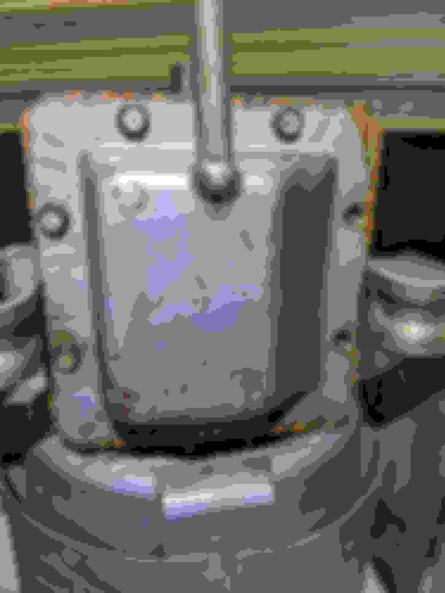
I took off what I only know to refer to as a valve cover and was greeted by this! It's got reeds in it! I'm not exactly sure of operational theory here, so if anyone knows I'd love to learn.
Then using a trusty spudger and rubber mallet I popped that guy off! Here's the underside of what is essentially the cylinder head. The left reed seemed pretty flat against the head. I intend to find out all I can on setting this back up as intended, but at present it's a mystery.
EDIT: Found an article explaining use of reeds instead of valves for 2-stroke motors. It explained that as the piston goes down and sucks air in, the reeds simply flex to facilitate entrance of said air. Then when the piston goes back up for compression, compression pushes the reed back up, closing the intake hole. The same concept is applied to exhaust, but the exhaust reeds are mounted on top of the combustion chamber rather than inside. It's my understanding that this design works on 2-strokes rather than 4 because 2-strokes take in air every time the piston goes down. Source Link
Continuing onward! *now may be a good time to tell you that I assume my problem is blow-by, and thusly, piston rings* Here we see the deck and pistons! Strikingly simple and likely pretty underwhelming to others. I've replaced a cylinder head before on a car, but never pulled a piston. This seemed like a good opportunity to demystify stuff! Since there isn't that much heat I dont think i'll have to deal with the head gasket. Will check later.
Here's the oil pan! (I'd already taken out some bolts)
And here's the crank! Note the little threaded studs sticking down. My best guess is that they churn up oil to get it onto stuff, cuz I don't think oil quite reaches the crank when filled appropriately.
Here's the crank again with one piston removed. had to hammer out the little tabs on the bolts that joined the piston rod around it. Etched the bolts first for later tightening :}
Here's a pic of the rod with focus on wear where it rides the crankshaft. It has light drag left and right play while assembled, no up n down.. I'd love to figure a way to make it fit better or replace it. Will be reading, forgive my ignorance!
At present I'm unsure if I'd need to bore the cylinders out to fix this thing or if there's rings available similar to high mileage head gaskets. I've heard modern compressors use plastic rings! This one's got metal..
I'll upload some video showing component motion or take some new pics tomorrow showing rings and such. Til then, have a good night folks!!