When you click on links to various merchants on this site and make a purchase, this can result in this site earning a commission. Affiliate programs and affiliations include, but are not limited to, the eBay Partner Network.
Wow, I'd thought this thread was dead and had stopped following; glad I checked back, lots of progress! I'm excited to find out there's a potential simple swap possible!
That has led me to another thought though. If all it takes is to swap out the module, no extra wires, then what is the FR-V stalk doing that my current one isn't? Presumably it's just a variable resistor on one of the leads for the INT setting, right? In which case, if I break that connection and install my own variable resistor in it can I replicate the variable speed option on the INT setting without having to pay a bunch of money for a new stick?
So, first question on that is, does anyone know of a wiring diagram for either of the two stalks anywhere? I'll check my own Fit manual when I get home, but I'm not sure if it goes into the details internal to the stalk itself. Anyone know where I might get one?
That would speed the process, but even absent that I might be able to reverse engineer it now knowing that the difference is so simple. Thoughts or suggestions are welcome, and if I get a solution I'll plan to post it. Thanks again to everyone for helping me make so much progress on this!
I would guess the same that the intermittent setting is likely a potentiometer that gives input to the timer. The same Element folks that were involved in the thread I linked above have another thread here that details a more DIY circuit that is likely similar to what you want. It might need to be adapted to the Fit, but I think it is the direction you are looking at.
Regarding the diagrams, the Fit ETM shows much of the wiring of the switch, but doesn't go into detail about the timer. Within the diagram for the switch it just has a box labeled "Intermittent Circuit" that connects to many of the outputs to the motor. Do you have access to the Fit ETM?
Within the diagram for the switch it just has a box labeled "Intermittent Circuit" that connects to many of the outputs to the motor. Do you have access to the Fit ETM?
Yes, I was looking at that yesterday, and rather annoyed that the circuit diagram just lists a box rather than showing the details of that circuit. As for a DIY alternative circuit, you and I actually found the same site (the one you linked to) for a potential alternative approach.
My sense though is that it might actually be better for me to skip entirely the "Intermittent Circuit" listed in the ETM diagram. If instead I replicate the "pulse" option (used when you push the stick up for a single wipe) then I can create my own variable intermittent option without having to break open any of the current electronics in the wiper stalk. Instead I'll just create an entirely new mode which creates a new intermittent option from repeated pulses. Thoughts on that? I'll probably have to do some testing on my current module to see what behavior I need to replicate, but it shouldn't be too bad I hope.
As noted before, if I reach a solution I'll plan to post it here for others.
Read some other posts about the connector at UDFP , do the GD have that or something similar? If so maybe I could try run 2 wires to it and give it a try.
My sense though is that it might actually be better for me to skip entirely the "Intermittent Circuit" listed in the ETM diagram. If instead I replicate the "pulse" option (used when you push the stick up for a single wipe) then I can create my own variable intermittent option without having to break open any of the current electronics in the wiper stalk. Instead I'll just create an entirely new mode which creates a new intermittent option from repeated pulses. Thoughts on that? I'll probably have to do some testing on my current module to see what behavior I need to replicate, but it shouldn't be too bad I hope.
I could see making a completely parallel switch and timer that would connect to the same wires as the existing switch. This would allow you to avoid having to get into the existing switch. However, there are a few possible pitfalls I can see with that:
1. It appears that the OEM "Intermittent Circuit" also handles returning the wipers to the parked position, so that is something you will have to duplicate in a possible alternative circuit.
2. If the new switch and the existing one were actually in parallel, there would be a possibility of voltage being applied to the low and high speed sides of the motor at the same time. It is unclear if this already happens in the existing circuit and whether it would be a problem if it did.
I could see addressing both of these issues by having a timer that triggers a latching relay circuit that would give power to the motor. The relay would be un-latched by voltage being applied to pin 12, which indicates the wipers are in the parked position. If it also turns-out that you need to avoid my issue 2 above, you could have the relay break the circuit of the existing switch (disconnect pin 2) when the relay is latched. You could even add a new feature by putting in a switch to control whether your relay is giving power to the low or high speed side of the motor. This would give a new option of intermittent timing with a high speed wipe, where the OEM only has low speed wipe with the intermittent setting. Does that make sense?
Originally Posted by feifei
Read some other posts about the connector at UDFP , do the GD have that or something similar? If so maybe I could try run 2 wires to it and give it a try.
I am not sure which post exactly you are referring to, but the approach I know of is the one for the Element. The Fit also has an under-dash fuse panel, but I can tell you it has completely different connectors than the Element fuse panel. What we really need to know to adapt that approach for the Fit is to know exactly what the purpose of those two pins is on the Pilot or RSX switch. Then we could see if there is an equivalent circuit(s) on the Fit and find which connector/pins they need to be connected to. I may have missed something, but I don't think the purpose of these extra pins was fully explained in the Element threads. The Pilot ETM would have the answer to this, but I don't have access to it.
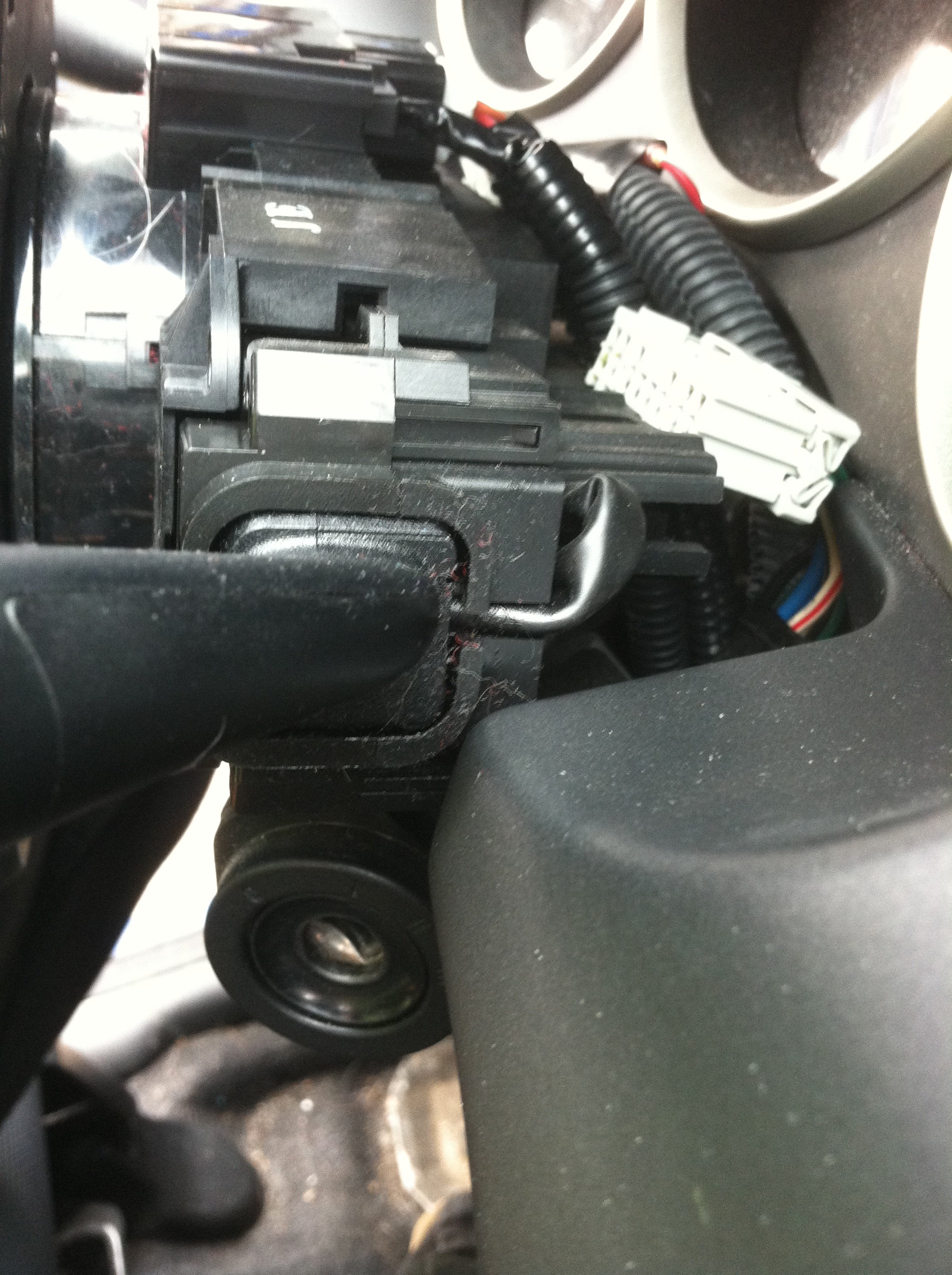
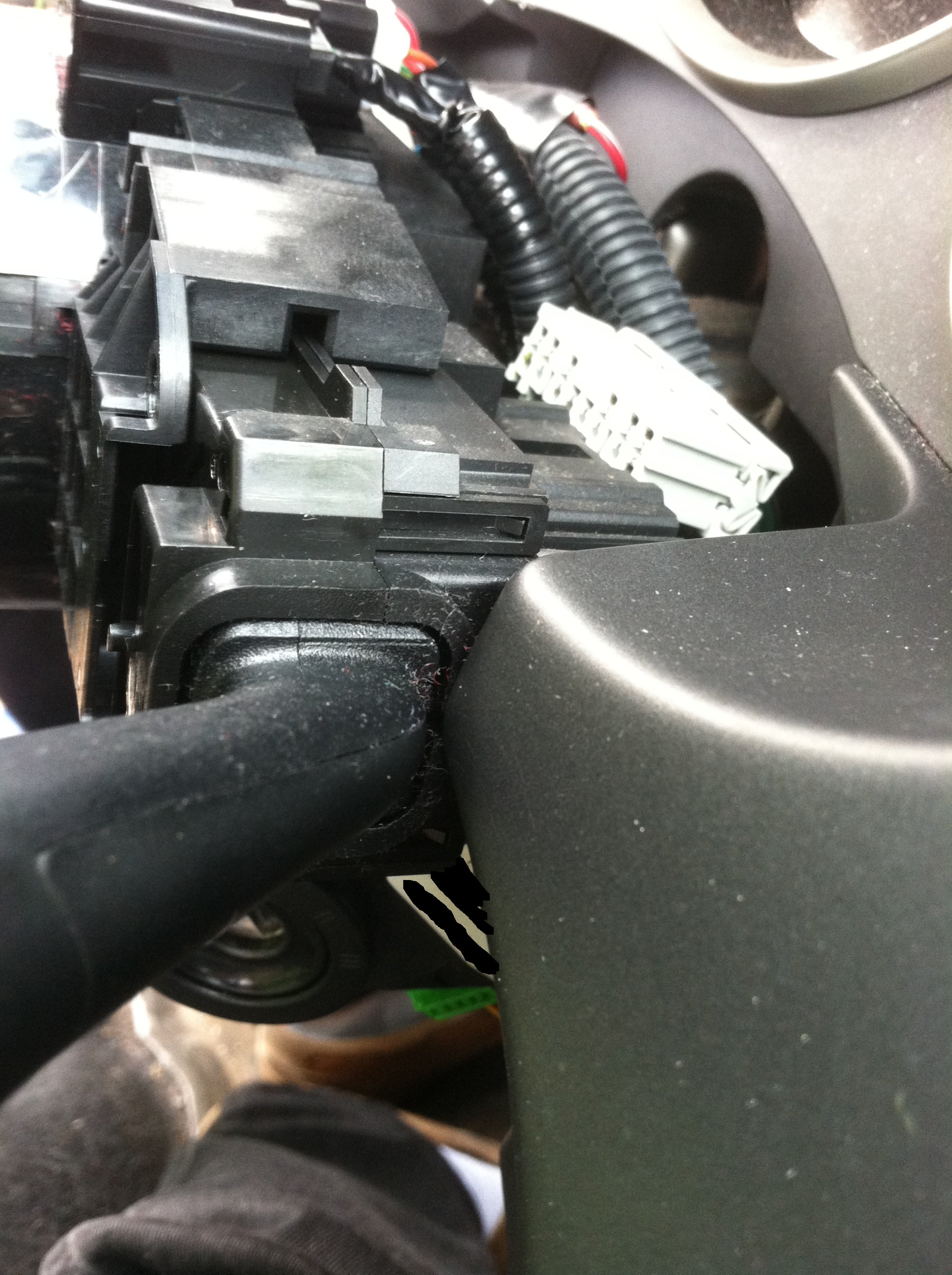
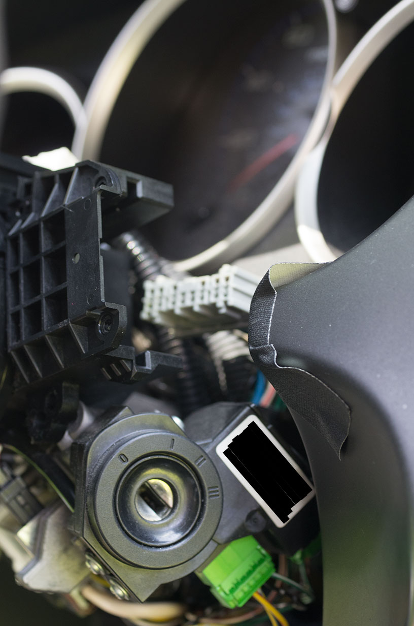
Some reasonable weather has arrived and I had some time to work on this, so I tried the wiper switch swap. I was not successful due to the fact that the Honda service manual is completely wrong about how to remove the switch! The manual states that only the steering column covers need to be removed to then be able to remove the wiper switch. As you can see from the pics below, that is not physically possible because a contour on the dash blocks the switch's path in both the max up and down position of the steering column. It appears that a complete removal of the steering wheel, cable reel, and combination switch is more likely the correct sequence! I have removed the steering wheel and cable reel in the past, but was hoping to avoid that this time. I am thinking that maybe if I remove the screws for the combination switch, it will allow me to pull it and the cable reel forward just enough for the switch to clear the dash contour.
@Mapone
How did you get the switch out and back in when you did it? Did you remove the steering wheel to get the clearance to remove the switch?
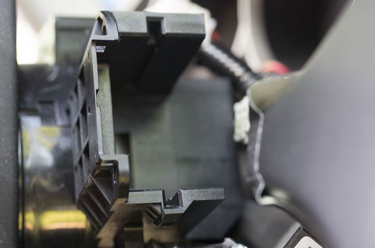
I finally got around to looking at this again, and I was successful in doing the switch swap without pulling the steering wheel! It seems that removing the screws for the combination switch does allow it enough play to just let the wiper switch pass the dash contour that blocks it when not loose. It is a very tight clearance though, and as you can see below, you will want to put some tape on the dash to prevent it from being scratched. The steering column must be in the all the way up position for the switch to clear the dash. As far as the intermittent timing, I have not had much chance to try it yet, but basic functionality seems to work, and the timing does seem to very with the new knob. So far so good!
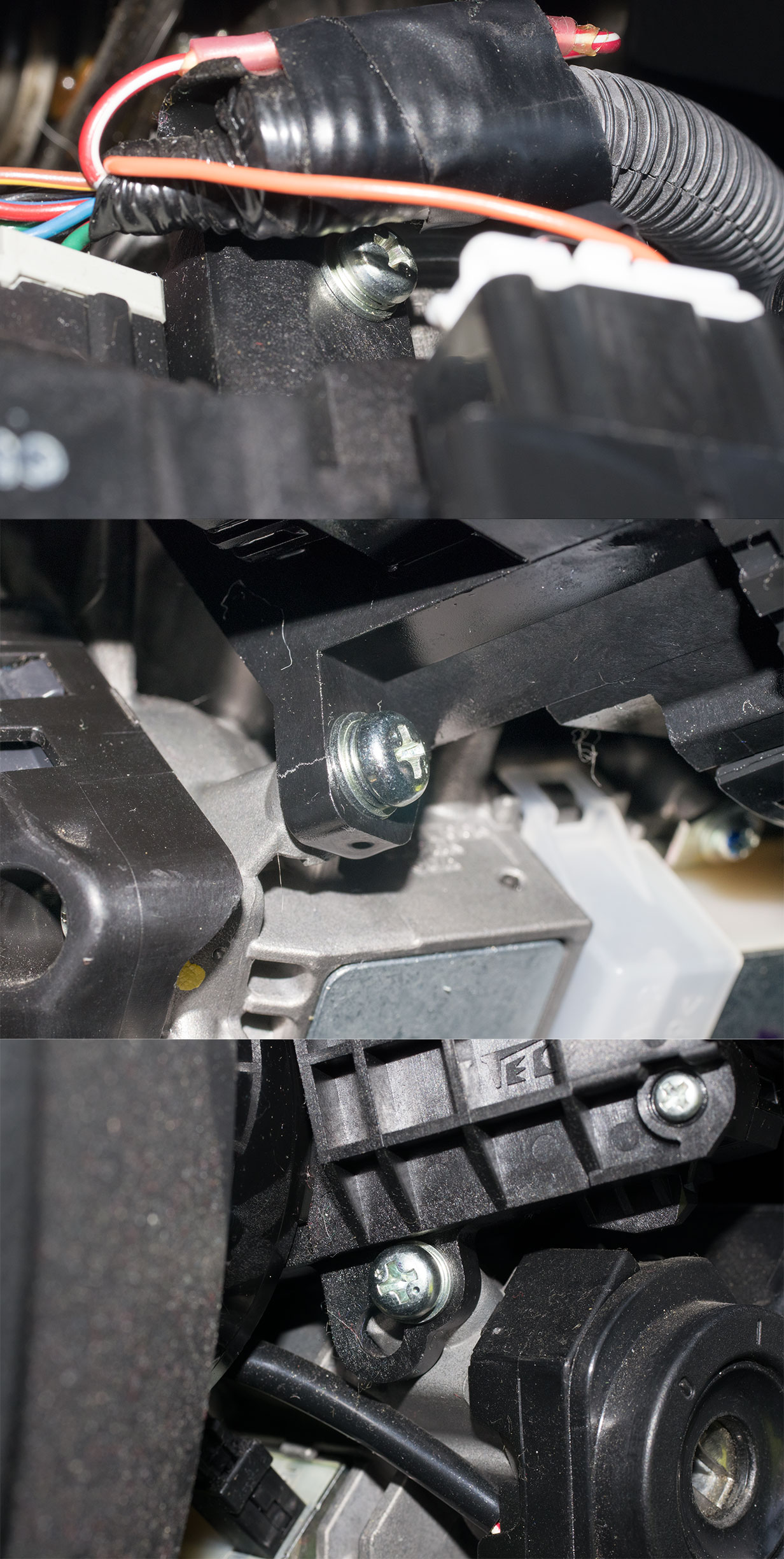
The screws to remove are in the following locations: on the top of the column behind the cable reel, under the column on the left facing the driver, and under the column on the right facing the driver. You will want to be careful when tightening the screws. I over-tightened one and cracked the plastic. Luckily the crack doesn't go all the way through.
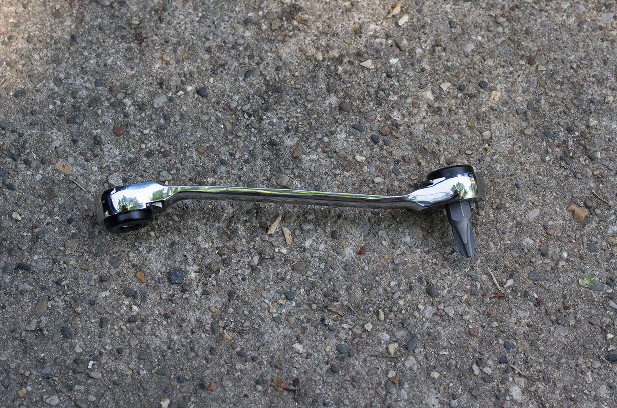
You will need a small right-angle Philips #2 driver like this one to get around the steering wheel which partially blocks access to the front screws:
Some pics of the switch removed:
Last edited by JBox; Jun 7, 2015 at 05:05 PM.
Reason: Added note about steering column position
Hi,
So what Jbox, where you successful? Did you get the FR-V one and installed it? Does it work like mine? I removed it all. Stering wheel, cable reel and complete combination switch. It just seems like easier way for me..
Hi,
So what Jbox, where you successful? Did you get the FR-V one and installed it? Does it work like mine? I removed it all. Stering wheel, cable reel and complete combination switch. It just seems like easier way for me..
I was able to get it working with the FR-V switch. So far it seems to work well and it is the same as yours. I am a happy camper!
The way I removed things was likely the same as you, except that I was able to loosen the combination switch without removing the steering wheel.
Has anyone opened up one of these to see if it's just a few missing components on the pcb? Doesn't really help without a pot on the stalk itself, but could be a cheap DIY.
Maybe I'll open mine once the FR-V one is installed
I just ordered a used FRV variable stalk from ebay, and noticed that it has a switch for fogs too. I have no fogs, I have an 08 LX MT with no fogs. Is the stalk going to work still?
Poking around on Amazon and it looks like the stalk for the Pilot (35256-S9V-A01) might work as well, although I can't seem to find any pictures of the back of the assembly to compare to those in this thread. The front looks identical. I think I'm going to do a little research this week, perhaps check out an auto wrecker or something to confirm.
It'd be nice to have a solution involving a North America-spec part number
Having it fit is only part of the battle, you need to make sure that it has the internal electronics within the stalk to control the intermittence. Many American models have stalks that physically fit but the electronics are external to the stalk. The GD3 has electronics that are internal to the stalk and only the FR-V has a part that fits and has the proper internals. But don't let me stop you, give it a try and report back.
Hi gys,
It's a bit old thread but yesterday I found the FR-V switch and after installing it INT didnt work.
It's actually AUTO on this switch.
Anyway, I opened both, and to my surprise in the FR-V wasn't any PCB inside.
I'm pretty sure that I can do wiring to the fuse box as in other models but has anyone opened the the one that directly replaces the original one?
Or any other ideas for wiring


 I have removed the steering wheel and cable reel in the past, but was hoping to avoid that this time. I am thinking that maybe if I remove the screws for the combination switch, it will allow me to pull it and the cable reel forward just enough for the switch to clear the dash contour.