
DIY: Power Inverter Install - Turn On with ACC (with pics)


Thread Starter
|
New Member
Joined: Oct 2013
Posts: 3
From: Winston-Salem, NC
DIY: Power Inverter Install - Turn On with ACC (with pics)
Project Overview
A power inverter converts 12V DC to 120 AC to provide power for common household electronics (i.e. cellphones, laptops). I located the inverter behind the passenger side dash. It is connected directly to the battery with proper sized wire with wire loom for protection. The inverter will turn on when the key is turn to the ACC position. NOTE: As a result, the inverter is always on while driving. Even if nothing is plugged in the inverter, there will still be a small load on the battery. I don’t know what that load is because I don’t have any measuring devices. I haven’t noticed any problems with my battery/alternator.
Materials Required
- Power Inverter
- 10.5ft of 10AWG wire
- 10ft of 16AWG wire
- 6ft of 18AWG wire
- 12V SPST/SPDT Relay
- Male Quick Disconnects w/ Heat Shrink
- Female Quick Disconnects w/ Heat Shrink
- 4x Ring Terminal for +/ 10AWG wire
- Honda AC Power Outlet (38520-TK8-A01ZD)
- Metal to make support brackets
- Heat shrink tubing
- Cable ties
- 15ft of 1/4" wire loom
- Mini Add-a-fuse
- Bolts, washers, nuts
- Wire stripper
- Wire crimper
- Heat gun/lighter/hair dryer
- Soldering iron
- Something to cut plastic (Exacto knife)
- Electrical tape
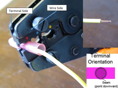
I used high-quality heat shrink terminals to make most of my wire connections. The heat shrink not only protects the wire from moisture but most importantly provides wire strain relief.
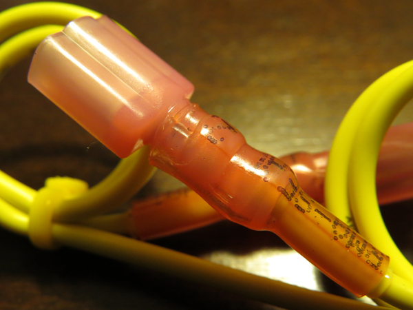
A crimping tool as shown below will provide a solid crimp, but they only work one way. The tool has a wire "in" side and a terminal side. Strip the wire to the length required for the terminal. Give the stripped wire a small twist (not too much). The terminal seam MUST point downward in order to provide a solid crimp. DO NOT over crimp, if you use a Blue wire/terminal in a Red die, too much pressure is applied and you may shear/break the wire. After crimping, give the terminal a slight tug to insure a strong connection was made. Use a heat gun (low setting) or lighter to shrink the heat shrink. Stop applying heat once you see glue oozing from terminal (wire side).
The end result will be a high-quality professional wire connection that will last as long as the car.
Inverter Modification
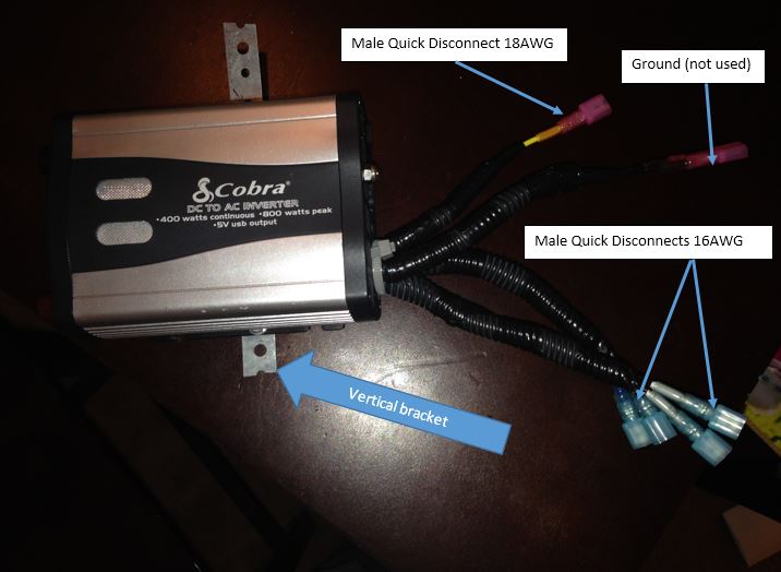
The Cobra 400 Watt power inverter worked well for this project as I could remove the plastic back plate and drill mounting holes. The inverter has some level of internal circuit protection to prevent overload and damage. Physical size of the power inverter is 6.4” x 4.2” x 2.6” which fit perfectly behind the dash on the passenger side (right of the glove box).
If you are using a different inverter, make sure it fits and doesn’t interfere with existing components (i.e. glove box, blower). My only gripe about the Cobra inverter is that when it turns on, the fan goes on high for 5 seconds, even without a load on it. The fan can barely be heard when the car starts; but to be honest, I’m probably the only person that hears it since I already know about it.
Outlet Wiring
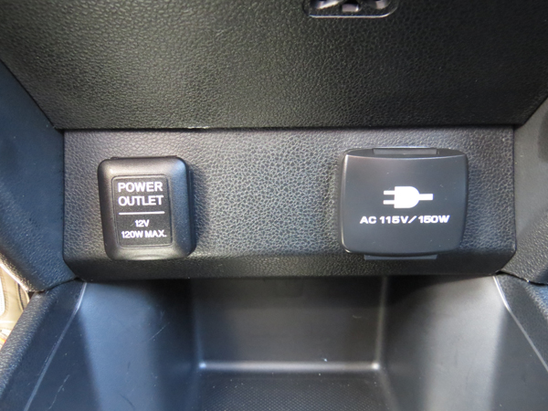
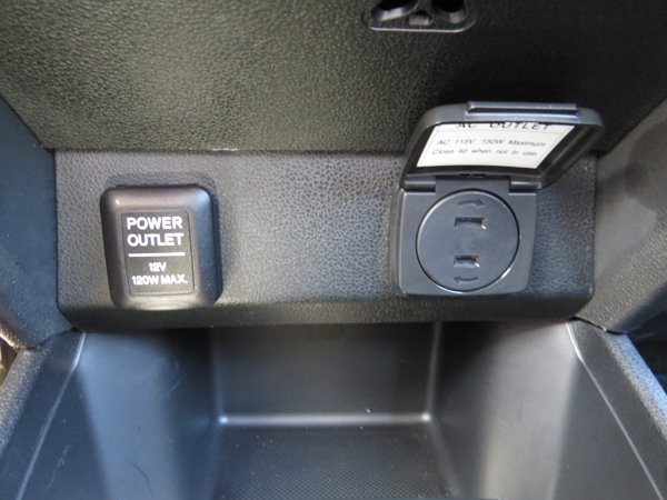
My inverter originally had 3-prong outlets that could be removed. At first, I was going to use the 3-prong outlets and buy a Honda DC outlet assy (39620-TA0-003) and use the housing with the 3-prong outlet. However, I think the 2-prong Honda AC outlet (38520-TK8-A01ZD) looks nicer and requires less modification. I didn’t hook up the ground wire from the inverter to anything. Remember, a ground wire is a safety feature used for high amperage devices (i.e. microwave, refrigerator). Those high amp devices would require not only a 3-prong outlet but also a larger inverter, larger battery, and larger alternator; this is a Fit, not an RV. And besides, by only having a 2-prong outlet in my car, it will prevent people from using high amperage devices in my car. I used two set of wires for 2 outlets: 1 for front passengers, 1 for rear passengers (future goal).
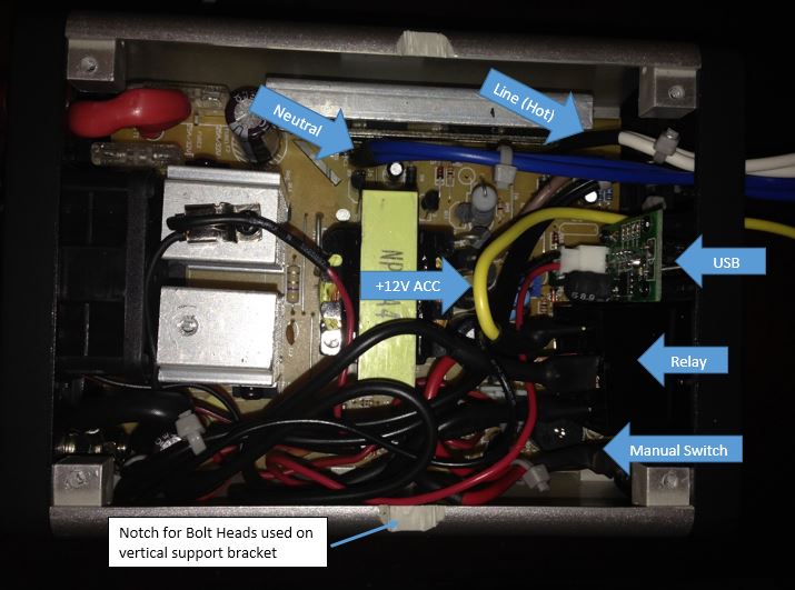
Inside the power inverter, I removed the previous outlet wires and soldered my wires in its place with male quick disconnects on the other end.
Relay Wiring
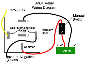
A relay is an “electronic switch”. It detects the +12V ACC voltage source and will “flip the switch” for the inverter, turning it on. I kept the manual switch in the circuit to give me complete override control to the inverter system. I used a single-pole double-throw SPDT relay, but an SPST could also be used as the “A” terminal is not used.
Car Wiring
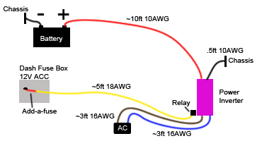
The positive wire is attached directly to the battery and the negative wire is attached to the chassis. Make sure to use a fuse when connecting the inverter directly to the battery. My inverter had a built-in fuse (most probably do). Theoretically, with 400 Watts at 12V, the inverter can draw 33 Amps. I used 10 AWG wire as determined by a chart like this.
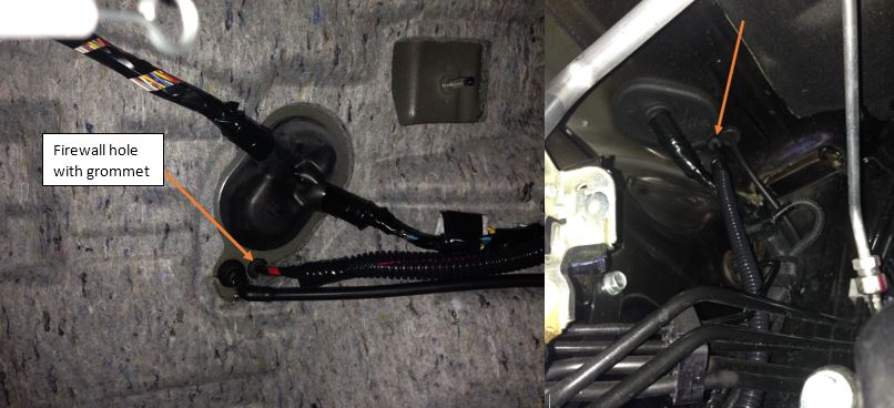
I ran about 10 ft of 10 AWG wire encased in 3/8” wire loom for protection. I should have used 1/4” wire loom but I didn’t have it at the time. I ran the wire close to existing wires, zip-tying it along the route (shown in orange). Route the wire away from hot objects (hot as in temp).
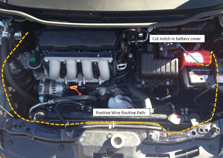
To gain access to the battery, I drilled a small hole in the passenger side firewall near an existing hole, behind the blower. You will first need to remove the blower (sorry, no pictures). For me, this was the most difficult part of the project. The only way I could get the blower out was by disassembling it while in the car. I removed the screws around the perimeter and took it out is 2 pieces.
Inverter Installation
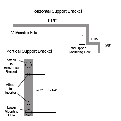
I didn’t have access to any metal cutting power tools so I had to make due. I used steel strip with holes found in the plumbing department. It is semi-strong and can be easily shaped by hand. The larger of the two holes allow for 1/4” bolts.
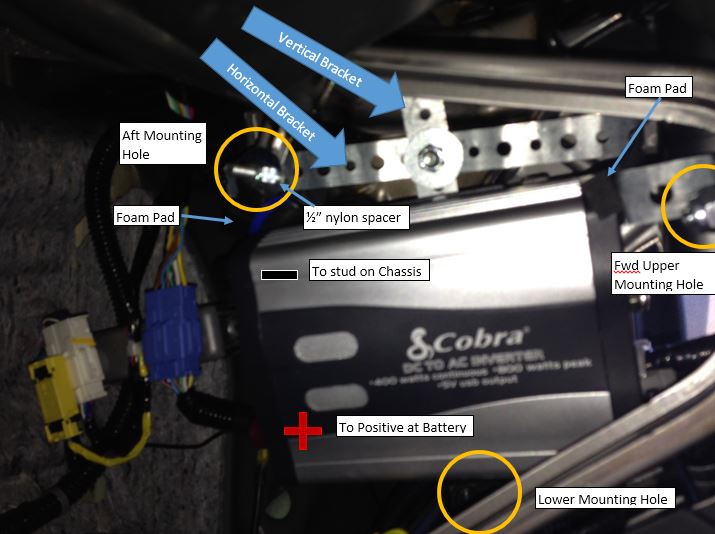
I created 2 brackets that attach at three points to the vehicle and attach to each other for a solid support system. I used foam pads to prevent vibrations (if any). I used a �” nylon spacer for the aft mounting hole to offset the horizontal bracket.
Make a short wire for the negative. Use a ring terminal and connect the negative wire to an existing ground on the chassis located near the installation
Outlet Install
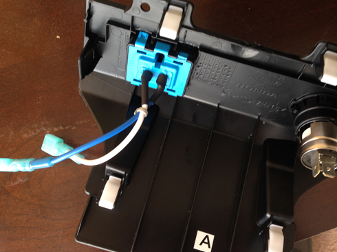
I made a paper template of the outlet (sorry, forgot dimensions). I drilled 4 small holes at each corner and used an Exacto knife to cut through the plastic. It’s very soft plastic and doesn’t take much effort. I used a small amount of epoxy to permanently secure the outlet to the plastic piece.
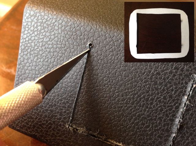
As you can see in the picture, I intentionally broke the blue plastic to expose the connectors. I soldered my wires directly to the connectors. The “correct way would be to buy the proper Honda connector and crimp the wires, but that seems like a lot of money for one task.
Now it’s ready to be installed in the car. Make some connector cables (~3 ft) with female quick disconnects at each end and connect them to the inverter.
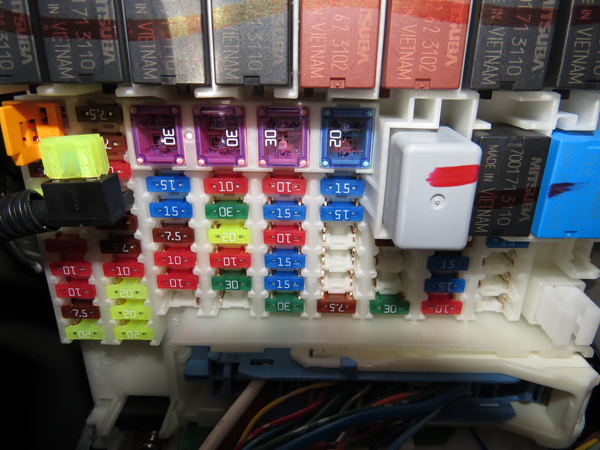
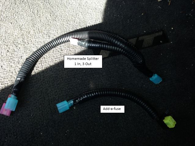
Use an Add-a-fuse Mini to get a +12V ACC voltage source. This will automatically turn the power inverter on when I turn the key to ACC. Install the Add-a-fuse in the ACC fuse slot. I made a splitter cable because I also have a dash cam being powered from the ACC fuse box. Make a wire (~5 ft) that connects the +12V ACC Fuse location to the +12V Relay in the inverter.
Last edited by mckee91; Mar 16, 2014 at 10:04 AM. Reason: Fixed formatting

Member
Joined: Apr 2012
Posts: 1,095
From: Hebron, In

Beautiful job and excellent DIY write up.
One small comment. The Honda FIT has an ELD (Electrical Load Detector). Wiring the inverter power input directly to the battery bypasses the ELD. If you start having a low battery problems you will have to move the power source for the inverter to the other side of the ELD so the computer raises the alternator voltage (and charge) to keep up with the inverter.
I really like what you did.

New Member

Joined: Apr 2011
Posts: 16
From: Merriam, KS
Beautiful job and excellent DIY write up.
One small comment. The Honda FIT has an ELD (Electrical Load Detector). Wiring the inverter power input directly to the battery bypasses the ELD. If you start having a low battery problems you will have to move the power source for the inverter to the other side of the ELD so the computer raises the alternator voltage (and charge) to keep up with the inverter.
I really like what you did.
One small comment. The Honda FIT has an ELD (Electrical Load Detector). Wiring the inverter power input directly to the battery bypasses the ELD. If you start having a low battery problems you will have to move the power source for the inverter to the other side of the ELD so the computer raises the alternator voltage (and charge) to keep up with the inverter.
I really like what you did.
Where is the ELD and where can I tie into the system to on the "other side" of the ELD?

Great DIY OP... +reps.
Been meaning to do this, I have all the parts, just haven't gotten around to it yet.
I was planning on putting the outlet in the rear hatch, but I think for my purposes the center console (in the rear), might be better.
My front panel already has an extra Aux outlet (I added the JDM cig lighter), and since mine's an 09 Navi, the aux input is there also.

Thread
Thread Starter
Forum
Replies
Last Post
12vltfrk
2nd Gen GE8 Specific Fit Interior Modifications Sub-Forum
8
Sep 30, 2009 08:10 PM
hogsniper
Fit DIY: Repair & Maintenance
9
Mar 13, 2008 06:22 PM