
Scoop Intake Build


Scoop Intake Build
So I somehow convince my Art Prof to let me build an "art intake" for the GD3. However due to the nature of the class, I must he make mold from of wood and metal model.
So my plan is to make a camber/scoop intake based out of the "gruppe m civic intake."
http://i137.photobucket.com/albums/q.../zzzzz7075.jpg
http://i137.photobucket.com/albums/q.../zzzzz2295.jpg
http://i137.photobucket.com/albums/q.../zzzzz2292.jpg
http://i137.photobucket.com/albums/q.../zzzzz2296.jpg
The material is going fiberglass or carbon fiber depending on looks, feel, and strength of the material.
(note that I'm going to abuse the school's machines, and assume the the fit's battery is moved to the trunk to make the build a lot of easier)
So my question is
1. How would different diameter of "intake tube" would effect the feel of the car (2.5 v.s 3inch Diameter)? Or the combo of the two?
2.How strong is a single layer of Carbon Fiber (speedwise, since it is a scoop design)?
3. How strong is fiberglass (speedwise, since it is a scoop design)?
4. How well is each of the material keep heat out from the motorbay (or a better way to ask is to how well does it keep the air cold). Or is it better to stick in an aluminum or a stainless steel tube instead for the "intake pipe?"
5. How doe air enter though the TB? Does it just suck in air from all directions or does a clockwise airflow, since I live in the upper hemisphere?
Thanks and sorry for the many question.
Last edited by Slimjimx701x; May 5, 2009 at 01:41 PM.
2.5inch intake tube would work fine as the 3 inch tube will make it bog a little at idle. (it does on my car)
fiberglass would be easier to make and i would say they are both pretty fragile.
they should both hold up even though its a scoop into the engine bay.
and they should both be able to reduce heat better than metal and cool down faster than metal since the dont really absorb the heat like metal. Also you have cold air being sucked into the scoop almost like a ram air so im sure it would keep air temp down and intake temp.
its a good idea and adds a little bling to the bay.
I just got the measurements for the MT as well. I'm planning to make this for both AT and MT for the GD
2.5inch intake tube would work fine as the 3 inch tube will make it bog a little at idle. (it does on my car)
fiberglass would be easier to make and i would say they are both pretty fragile.
they should both hold up even though its a scoop into the engine bay.
and they should both be able to reduce heat better than metal and cool down faster than metal since the dont really absorb the heat like metal. Also you have cold air being sucked into the scoop almost like a ram air so im sure it would keep air temp down and intake temp.
its a good idea and adds a little bling to the bay.
fiberglass would be easier to make and i would say they are both pretty fragile.
they should both hold up even though its a scoop into the engine bay.
and they should both be able to reduce heat better than metal and cool down faster than metal since the dont really absorb the heat like metal. Also you have cold air being sucked into the scoop almost like a ram air so im sure it would keep air temp down and intake temp.
its a good idea and adds a little bling to the bay.
Currently I'm still designing on the scoop intake interms of overall "art" and try to make it simple as possible...Less is more kind of thing. Another note I should add is that I would like to make fit with a turbo kit (just for kicks)
Last edited by Slimjimx701x; Apr 17, 2009 at 01:29 AM.
Funny how no one replied to your topic till I "mentioned" something.
Also, I have no keyboard at home, any replies you saw here, were done with the onscreen keyboard.
I found Ivan's OBD2 to USB adapter, and will most likely playing with it soon. But still working on some other things. Debt first.
I so want to get a KWSC once I have the stuff paid off, and then I can work on the Cold Air bit....
Hope it all turns out for the best... Let me know how it looks too. Try showing it to Manxman, he may have design ideas, he's good with that stuff.
Anthony, I'm passing the thread over to Dave...NOW
Sidenote, I need to take pictures of my motorbay without the battery and intake to see how much space is really there
Last edited by Slimjimx701x; Apr 18, 2009 at 02:02 AM.
Update:
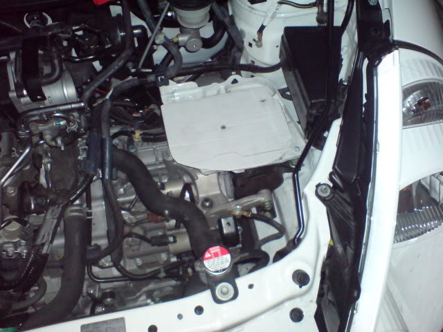
I took a picture of the bay and test fit some parts I took off some my friend's last build.
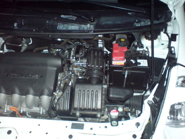
Stock Setup
Without airbox and battery (Look how much room there it") )
)
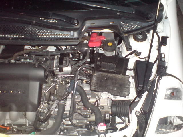
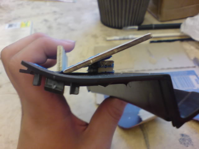
Test Fitting with 2.5inch pipe and 2.5inch filter (not so much room anymore )
)

With the test fitting, I know I can only fit half a foot of the 2.5inch pipe straight across from the TB if I want to place the filter right at the middle of the plastic trim. With the test fitting, I will not running a chamber intake that I planned earlier due the lack of lenght of the pipe. I would like to add that with that filter it takes up about one and a half inch of that tube to mount. I did not take measurements of how much space is remaining some the point after the filter (across from the TB), but I'm petty sure I have another half foot with my best guess.
After contacting with Dave, I will run somekind of reservoir bay with a 6mm hole to prevent hydrolocking (with the test fitting, I may be able to run a little more than a inch for the bay), and mess kind of item in the opening of the scoop to preventing rocks, bugs or tiny birds from entering.
Another thing I would like to mention after the test fitting is that I can use the bolt location of the OEM airbox for my under hood ducting. At this point I haven't decided to run a fully close duct (where there is no opening from the airbox to grill) or just a "flat" panel from the opening to the gril for a better ram air effect like "wontfit" mention.
I took a picture of the bay and test fit some parts I took off some my friend's last build.
Stock Setup
Without airbox and battery (Look how much room there it
)Test Fitting with 2.5inch pipe and 2.5inch filter (not so much room anymore
)With the test fitting, I know I can only fit half a foot of the 2.5inch pipe straight across from the TB if I want to place the filter right at the middle of the plastic trim. With the test fitting, I will not running a chamber intake that I planned earlier due the lack of lenght of the pipe. I would like to add that with that filter it takes up about one and a half inch of that tube to mount. I did not take measurements of how much space is remaining some the point after the filter (across from the TB), but I'm petty sure I have another half foot with my best guess.
After contacting with Dave, I will run somekind of reservoir bay with a 6mm hole to prevent hydrolocking (with the test fitting, I may be able to run a little more than a inch for the bay), and mess kind of item in the opening of the scoop to preventing rocks, bugs or tiny birds from entering.
Another thing I would like to mention after the test fitting is that I can use the bolt location of the OEM airbox for my under hood ducting. At this point I haven't decided to run a fully close duct (where there is no opening from the airbox to grill) or just a "flat" panel from the opening to the gril for a better ram air effect like "wontfit" mention.
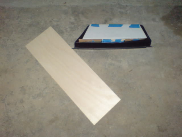
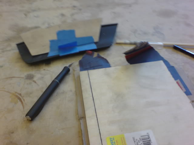
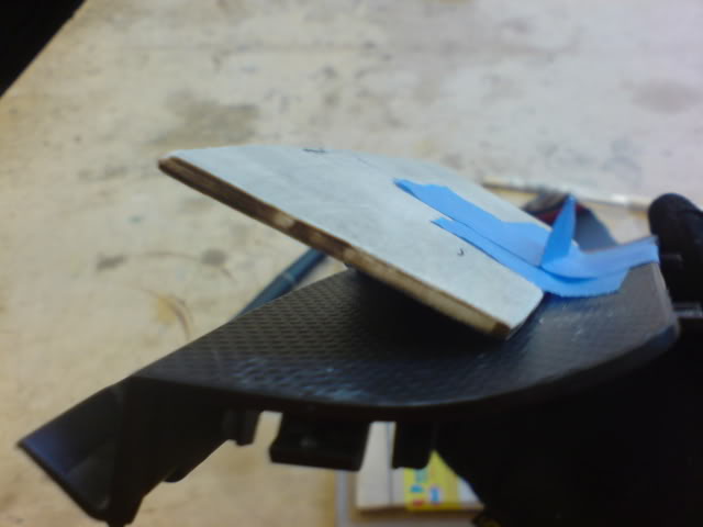
I started to work with the "scoop" part of the intake.
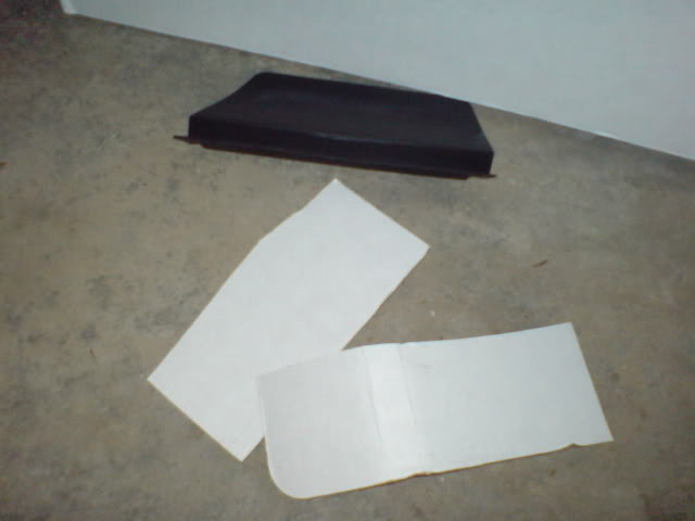
Some cardboard and the plastic trim
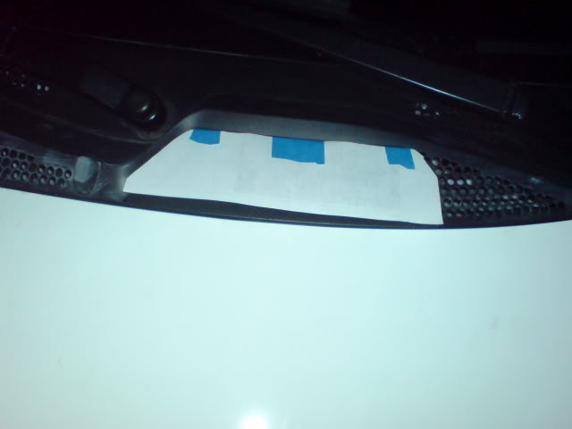
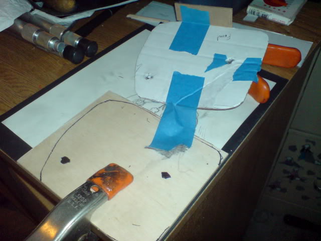
After abit of work, I use some paper to get the basic shape I wanted, so I can Bondo it later for a more better curve.
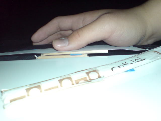
Used some chopsticks to help guide me on how high the scoop should be.
Now with cardboard cutout and one less piece of chopsticks.

May need to fill the hole...so the during vacuum it stay petty much the "finsh" shape
-NOTE, I'll be using an 1/8 inch thick plywood instead of cardboard.
P.S. basic concept design for the build
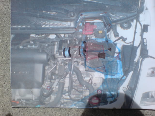
I'm thinking for the airbox itself, I'm going to make it out of carbon fiber, the nuts and bolts may have a bushed aluminum look or it can be powder coated with black, and everything else out will be flat-black painted fiber glass.
Edit:
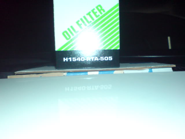
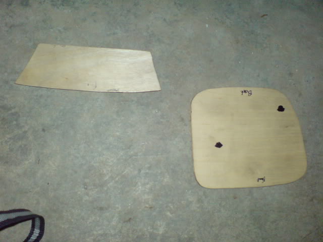
Started to work from paper to cardboard and then to plywood

MARKED!!!
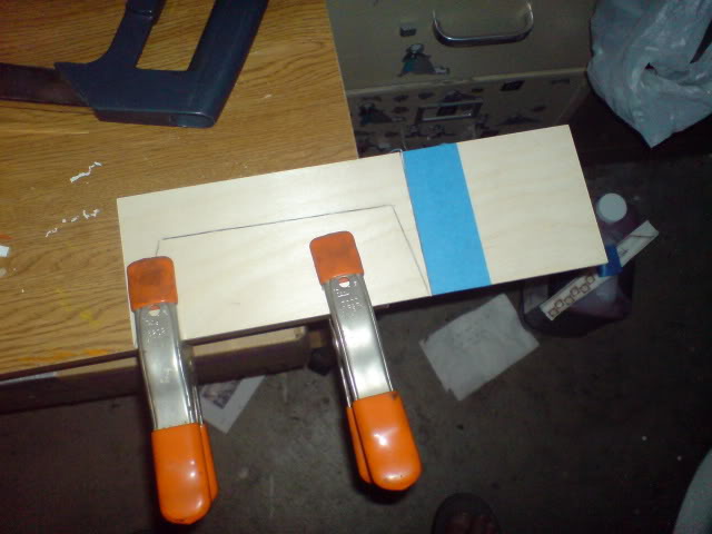
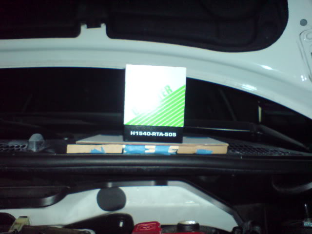
Working on the base of the airbox itself...
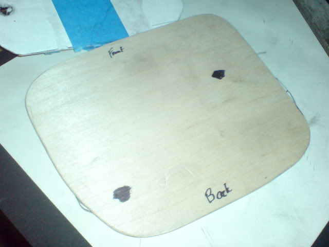
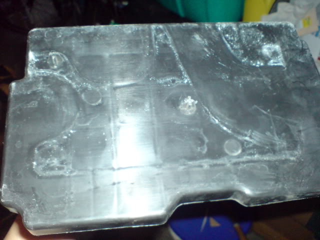
The black dots are for the peg, so I can reuse the battery tray
 Done....for now
Some cardboard and the plastic trim
After abit of work, I use some paper to get the basic shape I wanted, so I can Bondo it later for a more better curve.
Used some chopsticks to help guide me on how high the scoop should be.
Now with cardboard cutout and one less piece of chopsticks.
May need to fill the hole...so the during vacuum it stay petty much the "finsh" shape
-NOTE, I'll be using an 1/8 inch thick plywood instead of cardboard.
P.S. basic concept design for the build
I'm thinking for the airbox itself, I'm going to make it out of carbon fiber, the nuts and bolts may have a bushed aluminum look or it can be powder coated with black, and everything else out will be flat-black painted fiber glass.
Edit:
Started to work from paper to cardboard and then to plywood
MARKED!!!
Working on the base of the airbox itself...
The black dots are for the peg, so I can reuse the battery tray
Done....for now
Last edited by Slimjimx701x; Apr 22, 2009 at 02:02 AM.
He's not going to stop that... he's gonna let it out from the bottom of the scoop..
that's the whole point of the design.... it's not like it's a direct line to the intake... it's a scoop.
that's the whole point of the design.... it's not like it's a direct line to the intake... it's a scoop.
Merchant / Group Buy Organizer ( non-certified )
iTrader: (20)
Joined: Mar 2008
Posts: 307
From: Casa Grande, AZ
It would be nice to see someone follow through with this, it's the basic concept I wanting to do when I started the cowl scoop, but there just didn't seem to be enough interest.
Let me know if you need a hand with anything.


Let me know if you need a hand with anything.
Oh wow, thanks Rouge Fit. I will get in touch with you once I get done with the molds....I have a feeling that I'm still going to mess up with the CF. Just wondering how many layers did you use for those scoops? Three? Thanks
I'm not going to stop it, IF it start getting into rain season I'll just run those filter covers on the jet ski (AEM or KN got one)
http://kandn.com/images/l/RU-0520PK.jpg
Plus, I did plan to use a air bypass valve as well
Update.
Decide to add a bit more shape at rear of the scoop...old idea look to flat.
Need to retirm the main parts
Maybe temping to make the add on a bit smaller..or just wait till i get the clay and shape it later...IDK yet.
Last edited by Slimjimx701x; Apr 22, 2009 at 11:00 PM.


Merchant / Group Buy Organizer ( non-certified )
iTrader: (20)
Joined: Mar 2008
Posts: 307
From: Casa Grande, AZ
Keep up the good work.