
Glove Box light

Aw hell, quit teasing and show us your titties! Oh, sorry wrong discussion, I mean how much for one of yours. I figure this ain't only for the fit, as a business man, you've obviously looked over the configurations of all the upcoming and current models to see where the market is and how to reach that demographic. So how much and will we soon see you on TV?
 Actually My wife and I are furniture/space designers. The lack of a glovebox light in the Fit was just something I wanted to remedy. So I spoke about it with a company in Asia I worked for before who deals in electronics and hand tools among other things. they are the ones who are making this light. they've just been asking my opinions on things since I was the one who brought up this product, and I've done some side projects in automotive lighting work such as custom LED and HID retrofits. We also incorporate lighting elements into many of our furniture and home decor item designs.
 So until the company has a prototype, I really got nothing to show you yet. But if you really want to see my pierced titties instead, we'd probably need to move to the wasteland sub-forum.

Keep in mind though that most automotive electrical systems are running not 12V, but around 14.5V when the alternator is cranking. Many cheap replacement LED bulbs burn out prematurely due to this reason. It's much better to underdrive an LED than to overdrive it. If I was doing an entire LED taillamp board, I'd definitely use a solid state voltage stablizer. In this case, just a couple of LEDs to light up a glovebox, I'd just make sure that you calculate the needed resistor from 14.5V instead of 12V.
Although I still don't understand why you'd hard wire in something that's designed to be stuck on with double-side tape and be done. If you're going to bother with wiring, you'd have much better control of the light dispersion, intensity, and mounting location just mounting a few LEDs on a PC board and wiring an alarm type magnetic switch to be mounted right at the opening. Because that's the problem with using a magnetic switch, it only works in very close distance.
Anyways, here's a couple of link for your reference of someone adding LEDs to light their glovebox in their Odyssey:
LED Glove Box Light Mod
someone else added a push-pin switch to the circuit:
OdyClub Forums - Led glove box mod add-in
It would be the same principle to wire in a magnetic switch instead. (same as door pins for interior lights)
Hope this helps.

Member
Joined: Jun 2007
Posts: 32
From: Los Angeles, CA
To drive 2 LEDs, even 14 gauge is probably overkill. Even the wires for the reverse lights are probably only 18ga, and they draw more current than your LEDs ever will. And since the LED's current draw will be in milliamps (mA), a 15A fuse will protect nothing. Your LEDs will pop WAY before the fuse blows.
Although I still don't understand why you'd hard wire in something that's designed to be stuck on with double-side tape and be done. If you're going to bother with wiring, you'd have much better control of the light dispersion, intensity, and mounting location just mounting a few LEDs on a PC board and wiring an alarm type magnetic switch to be mounted right at the opening. Because that's the problem with using a magnetic switch, it only works in very close distance.
I'm going to focus on fishing the line over, then sort out why.
Last edited by stephanpark; Jun 23, 2007 at 03:54 PM. Reason: Removed Tourette's cursing.

Member
Joined: Jul 2007
Posts: 1,584
From: Memphis, TN

I believe both autolumination.com and superbrightleds.com sell them
Member
Joined: Jun 2007
Posts: 32
From: Los Angeles, CA
I ended up finding what I wanted in this post.
https://www.fitfreak.net/forums/fit-...ht=glove+light
LDO did an install that felt a bit warranty-killing to me but it was the most effective mod of those discussed here. Simple to think about but a nightmare to actually do. His details were good but I found a lot needed mentioning as this is more difficult an mod than it sounds.
So here goes.
FIRST: Take the front dash off. Why? Oh boy. In my case, I had a stepped drill bit at my disposal so just punching through willy nilly was just NOT an option because, the dash support frame is made of hard metal with a rounded surface that a bit will slide off unless you catch it exactly at the tangent facing the bit. So, it requires the removal of a trim piece on the left side of the glove box opening shown below in LDO's thread. No mean feat. Lucky(?) for me, I was installing an iPod integration on the head unit so it was the second bird.

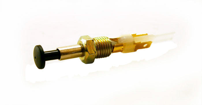
THIRD: Drill a hole in the metal frame in desired location (scary). The lower the better to ease closure by way of increased leverage on the push switch. I indented with punch and hammer to give better purchase then went at it with a stepped. Bonus point: make the hole just a bit smaller than the stitch cylinder, thread with the right tapping tool to eliminate need for backing nut. (P.S. 3/8-24 nut for the model from Adjustable Door / Hood Pin Switch)
FOUR: Make hole in the trim panel that was removed. I'd suggest you reinstall sans screws. Take a sharpie and mark using the hole from step three on the back side of the trim panel making sure you are as tangent as possible with that curving metal frame. This way you don't need to guess where to best make that hole. Remove trim panel and make that hole at the recommended 5/16" (or smaller, but then you'd be on your own).
FIVE: Install a mini-fuse tap (not regular sized) into the under-hood fuse box. Remove ground terminal from battery. Safety first! Remember to take note of your radio code.
Locate fuse box on driver's side (triangular box) and install fuse tap along with a mini fuse, I used 7.5 amp as well as the 10 amp the fuse tap replaced.
Place the mini-fuse tap in slot 8 used for "Audio unit, Ceiling light, Data link connector, Gauge assembly, Immobilizer control unit-receiver, Immobilizer code unit, Keyless receiver unit, Navigation unit, Spotlights, Tailgate light".
This one is always hot and isn't mission critical to car operation. Here is a picture of a fuse tap you can get at your local Auto Pep Super Mart Zone Boys.

SIX: Route a 16 gauge wire (I like red) from your new battery tap line to a rubber diaphragm thing holding a wire harness on the passenger side of the firewall. I made a tiny hold on the upper end of the diaphragm and passed the wire through, contortion necessary. From the passenger compartment's passenger side, you'll notice a wire peaking through on the lower right side of the circulation fan motor under the dash area. Route that wire up to somewhere near your new switch's hole. I used many nylon tie downs, sticker wire clips, wire labels and a smattering of bullet connectors. You should use your own judgment on installation of your line as engine heat and subsequent Honda Servicing will need to be considered.
SEVEN: Install the switch and light.
Reinstall the glove box trim piece with the new hole and then install the switch. Depending on whether you gone for the bonus points in step 3 you'll need to disassemble and reassemble in a way best for your situation.
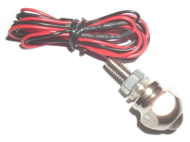
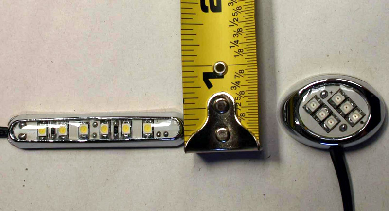
Put terminal connector that mates to your switch's on the ground/negative wire from your choice of LED light. I used this below from Oznium because of it's good spread of light (too much actually), its low profile and the combined shipping with my switch from the same guys.
On the wire you've just fished through the bowels of hell, attach a connector to it then connect it to your LED's positive wire. In my case I use a bullet connector (female for safety), then made and adapter to connect to the LED module because I plan to install a 12V socket in there someday. Your wiring can be much more direct.
FINALLY: Put Humpty Dumpty back together again.
Install the panel in the reverse order of removal, and make sure each connector is plugged in properly, and antenna lead and cables are connected properly.
DONE!!!!
This write up is meant to scare off those of weak constitutions and encourage the more die hard tinkerers.
https://www.fitfreak.net/forums/fit-...ht=glove+light
LDO did an install that felt a bit warranty-killing to me but it was the most effective mod of those discussed here. Simple to think about but a nightmare to actually do. His details were good but I found a lot needed mentioning as this is more difficult an mod than it sounds.
So here goes.
FIRST: Take the front dash off. Why? Oh boy. In my case, I had a stepped drill bit at my disposal so just punching through willy nilly was just NOT an option because, the dash support frame is made of hard metal with a rounded surface that a bit will slide off unless you catch it exactly at the tangent facing the bit. So, it requires the removal of a trim piece on the left side of the glove box opening shown below in LDO's thread. No mean feat. Lucky(?) for me, I was installing an iPod integration on the head unit so it was the second bird.
1. Remove the inner glove box to get access to vent control lines.
For US model Fit, they will have a full Glovebox-in-door. There are screws at each hinge of the two hinges at the bottom. Remove these while keeping the lock hold the door in place. Unlock to open door. There are two catch tabs with rubber stoppers at the rear of top of the door bin, press both left or right tab in gently to release the door from dash.
Open the glove box lid, then gently pull out the inner glove box (A) to detach the clips, then remove it.
To reinstall, insert a rib (B) on back of the box to the holder (C) of the steering hanger beam.
2. Remove passenger's side dash under cover on the right side (Driver's side shown though).

Turn the lock knob (B) 90�. Gently pull down the rear edge to release the clip. Pull the cover away to release it from the clip (C) on the body and to release its pin (D) from the kick panel (E).
3. Remove the screw (A). Detach the clips (B) and release the hooks (C) by pulling the center lower cover (D) down, by hand.
Disconnect the heater control unit connectors (E) or climate control unit connector, and release the unit harness (G) from the clamp.
TIP: Try to pull down from the edges near the clip once you have the screw off. As a lot of force (30+ lbs.) is necessary to get it off, put some padding over your stick or auto-knob.
4. In the inner glove box opening, disconnect the recirculation control cable (A) and the mode control cable (B), and from under the dashboard, disconnect the air mix control cable (C). Take care not to bend any cables and also label the position with a permanent marker as this is important when reinstalling with lines at the same length they were.
5. IMPORTANT! From the glove box and driver's dashboard lower cover openings, loosen the bolts securing the center panel (A). (note: Illustration shows Automatic AC unit but bolts are in same location)
6. Using a wrench, carefully insert a wrench from the inner glove box opening, and push a panel clip on the glove box side from back of the center panel (A) to release it.
7. Pull out the center panel (A) to release the clips (B, C), and disconnect the connectors. Heater control switch connector (D) and rear deffoger switch connector (E) then, Audio unit connectors (F) and antenna lead (G).
 TIP: Go out and buy a set of these clips from your local Honda dealer. They are cheap and should always be in stock. Unfortunately I didn't and step 7 will most definitely mangle at least 2. I had to bend them back into shape and blew 20 minutes getting them right.
8. Detach the harness clips (K) from both center panel brackets, then remove the center panel. Take care not to bend any cables.
SECOND: Remove that trim piece on the left by removing two screws who's heads will be facing away from you in behind the dash. There are on the upper left corner and are extremely hard to access because they were never meant to be removed in this way. You will need an extremely short philips driver for the top right one of the two. I used a ratchet wrench bit, mated it to a philips driver bit then added a 1/2 adapter for more leverage, anything bigger just won't fit...not even a stubby philips driver. And then remove the trim piece. Good luck.For US model Fit, they will have a full Glovebox-in-door. There are screws at each hinge of the two hinges at the bottom. Remove these while keeping the lock hold the door in place. Unlock to open door. There are two catch tabs with rubber stoppers at the rear of top of the door bin, press both left or right tab in gently to release the door from dash.
Open the glove box lid, then gently pull out the inner glove box (A) to detach the clips, then remove it.
To reinstall, insert a rib (B) on back of the box to the holder (C) of the steering hanger beam.
2. Remove passenger's side dash under cover on the right side (Driver's side shown though).
Turn the lock knob (B) 90�. Gently pull down the rear edge to release the clip. Pull the cover away to release it from the clip (C) on the body and to release its pin (D) from the kick panel (E).
3. Remove the screw (A). Detach the clips (B) and release the hooks (C) by pulling the center lower cover (D) down, by hand.
Disconnect the heater control unit connectors (E) or climate control unit connector, and release the unit harness (G) from the clamp.
TIP: Try to pull down from the edges near the clip once you have the screw off. As a lot of force (30+ lbs.) is necessary to get it off, put some padding over your stick or auto-knob.
4. In the inner glove box opening, disconnect the recirculation control cable (A) and the mode control cable (B), and from under the dashboard, disconnect the air mix control cable (C). Take care not to bend any cables and also label the position with a permanent marker as this is important when reinstalling with lines at the same length they were.
5. IMPORTANT! From the glove box and driver's dashboard lower cover openings, loosen the bolts securing the center panel (A). (note: Illustration shows Automatic AC unit but bolts are in same location)
6. Using a wrench, carefully insert a wrench from the inner glove box opening, and push a panel clip on the glove box side from back of the center panel (A) to release it.
7. Pull out the center panel (A) to release the clips (B, C), and disconnect the connectors. Heater control switch connector (D) and rear deffoger switch connector (E) then, Audio unit connectors (F) and antenna lead (G).
TIP: Go out and buy a set of these clips from your local Honda dealer. They are cheap and should always be in stock. Unfortunately I didn't and step 7 will most definitely mangle at least 2. I had to bend them back into shape and blew 20 minutes getting them right.8. Detach the harness clips (K) from both center panel brackets, then remove the center panel. Take care not to bend any cables.
THIRD: Drill a hole in the metal frame in desired location (scary). The lower the better to ease closure by way of increased leverage on the push switch. I indented with punch and hammer to give better purchase then went at it with a stepped. Bonus point: make the hole just a bit smaller than the stitch cylinder, thread with the right tapping tool to eliminate need for backing nut. (P.S. 3/8-24 nut for the model from Adjustable Door / Hood Pin Switch)
FOUR: Make hole in the trim panel that was removed. I'd suggest you reinstall sans screws. Take a sharpie and mark using the hole from step three on the back side of the trim panel making sure you are as tangent as possible with that curving metal frame. This way you don't need to guess where to best make that hole. Remove trim panel and make that hole at the recommended 5/16" (or smaller, but then you'd be on your own).
FIVE: Install a mini-fuse tap (not regular sized) into the under-hood fuse box. Remove ground terminal from battery. Safety first! Remember to take note of your radio code.
Locate fuse box on driver's side (triangular box) and install fuse tap along with a mini fuse, I used 7.5 amp as well as the 10 amp the fuse tap replaced.
Place the mini-fuse tap in slot 8 used for "Audio unit, Ceiling light, Data link connector, Gauge assembly, Immobilizer control unit-receiver, Immobilizer code unit, Keyless receiver unit, Navigation unit, Spotlights, Tailgate light".
This one is always hot and isn't mission critical to car operation. Here is a picture of a fuse tap you can get at your local Auto Pep Super Mart Zone Boys.
SIX: Route a 16 gauge wire (I like red) from your new battery tap line to a rubber diaphragm thing holding a wire harness on the passenger side of the firewall. I made a tiny hold on the upper end of the diaphragm and passed the wire through, contortion necessary. From the passenger compartment's passenger side, you'll notice a wire peaking through on the lower right side of the circulation fan motor under the dash area. Route that wire up to somewhere near your new switch's hole. I used many nylon tie downs, sticker wire clips, wire labels and a smattering of bullet connectors. You should use your own judgment on installation of your line as engine heat and subsequent Honda Servicing will need to be considered.
SEVEN: Install the switch and light.
Reinstall the glove box trim piece with the new hole and then install the switch. Depending on whether you gone for the bonus points in step 3 you'll need to disassemble and reassemble in a way best for your situation.
Put terminal connector that mates to your switch's on the ground/negative wire from your choice of LED light. I used this below from Oznium because of it's good spread of light (too much actually), its low profile and the combined shipping with my switch from the same guys.
On the wire you've just fished through the bowels of hell, attach a connector to it then connect it to your LED's positive wire. In my case I use a bullet connector (female for safety), then made and adapter to connect to the LED module because I plan to install a 12V socket in there someday. Your wiring can be much more direct.
FINALLY: Put Humpty Dumpty back together again.
Install the panel in the reverse order of removal, and make sure each connector is plugged in properly, and antenna lead and cables are connected properly.
DONE!!!!
This write up is meant to scare off those of weak constitutions and encourage the more die hard tinkerers.
Last edited by stephanpark; Dec 12, 2007 at 07:57 PM.
Member
Joined: Sep 2007
Posts: 172
From: Pensacola, Fl
Stephen,
Glad my mod got your brain wheels turning. I apologize (as I did in my original post) for the lack of detail and pictures (step by step stuff) but my assistant, who normally takes all the pics, was out shopping with the kids and I only had a couple of hours to get this done.
I don't think there's much to worry about with regards to warranty issues unless your car burns down due to an electrical fire caused by faulty or inproperly routed wires....
Looks good. I don't recall having to tear down so much of my car but I can see where having alot of stuff torn down would keep more skin on my knuckles!
LDO out.
Member
Joined: Jun 2007
Posts: 32
From: Los Angeles, CA
Thanks much LDO, I had seen your post and just actually caught myself saying out loud, "perfect!". Totally chucked my ideas out in favor. But I had trouble along the way an so the writeup. Hm, since I'm doing three mods at once, I couldn't imagine how to port the hole into the metal frame without the plastics all removed and out of the way. Oh, an air can and a vacuum during cleanup was also helpful to get the metal and plastic bits out...you know, for the barefoot car passengers.
Some notes on the time frame since you bring up an excellent point...how long does it all take and cost.
2 minutes - Removing minimal plastics (Glovebox/door)
10 minutes - Removing dash under parts
30 minutes - Removing center dash (head unit and climate control nacelle) VERY VERY HARD TO REMOVE!!!
1 hour - Installation of fuse tapper and wire routing.
20 minutes - Wire prepping and switch/light installation.
Mod Shopping List: your costs may vary, no shipping costs included
$9.99 - LED Module
$6.99 - Pin Switch
$0.15 - 7.5 Amp Fuse
$4.00 - Spare Honda clips (aprox)
$3.00 - 14 or 16 Gauge red wire ~12 feet
$5.00 - Box of male and female bullet connectors
Tools Used:
Power Drill - with Stepped carbide bit
Screw Driver- Philips Bit
Stubby Driver - Philips Bit
Socket Wrench - with extension 10" (used only in "FIRST" section step 6)
*I used what I had...a 5" extension to step down adapter to a socket screw tipped with a small socket.
Dremel Tool
Small Vacuum
Air Can
Small Mirror & Headlight or Flashlight (useful for "FIRST" section step 5)
Scotch Blue Tape 1"
Nitrite gloves
That should cover it.
Last edited by stephanpark; Dec 12, 2007 at 11:44 PM.

Member
Joined: Jan 2013
Posts: 125
From: Ca
How can you write such an amazing DIY and not take any good pictures? I would LOVE to have seen the finished product and the steps throughout. But because there were no pics (I'm a visual learner) I'm going with the easy option http://www.asseenontv.com/detail.php...5d906391c1bd72
Last edited by Mikeyk12; Jan 31, 2013 at 12:01 AM.

Thread
Thread Starter
Forum
Replies
Last Post
Vash
2nd Generation (GE 08-13)
3
Apr 2, 2014 12:10 PM
StewNTexas
2nd Gen GE8 Specific Fit Interior Modifications Sub-Forum
2
Apr 18, 2012 11:34 AM