When you click on links to various merchants on this site and make a purchase, this can result in this site earning a commission. Affiliate programs and affiliations include, but are not limited to, the eBay Partner Network.
Here is the link CAR8.com �L**���� -- �s��ԲӸ��
this is for sale too...$2000 HKD
If you want it you might need a Chinese friend to hook you up
It said like new, Japan version very rare else...
Hi New to the forum, and really interested in doing this.
I have a 2011 Honda Fit Sport but no Navi. I'm definitely interested in getting the steering wheel controls installed, but is it possible without the navi?
I'd really love to order that one part pictured above, 36770-tk6-a41 but would it work with my not-navi fit? I just want it to match and work correctly.
I had recently gotten my first oil change, and asked about it at a dealer. They said theres no way for me to get it installed from them... Kinda bummed me out.
Just looking for the easiest way to do it! Thanks in advance!
yes it is possible.
please go back and read the whole DIY. It explains everything.
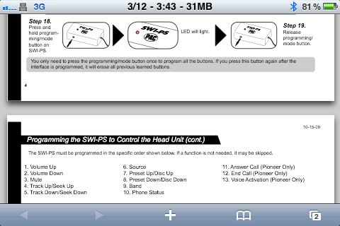
The bluetooth functions with this deck are NICE! If I REALLY wanted too, I could get the PAC wireless adapter and program the bluetooth signals from the JVC wireless remote and program them to work with the NAV buttons, but that's more money and not really needed.
@b17gsr, I noticed that you wired out your bluetooth signal all the way to the headunit, but didn't actually connect it to anything. Have you considered upgrading your SWI-JACK to a SWI-RC, and wire together the two signals (audio controls and bluetooth) to connect to the SWI-RC input? That should give you bluetooth control on your JVC KD-AVX33. I'm planning on doing that type of install on my 2007 Fit Sport Manual with a Pioneer DEH-P8400BH.
A quick question: why did you remove wires from the new subharness and install onto the old subharness, instead of simply replacing the old subharness with the new? Are the white connectors different, or are the pinouts different? I have pinned-out the new subharness I bought from jdmparts.com, but haven't pinned-out the old subharness, which won't happen until I start taking things apart.
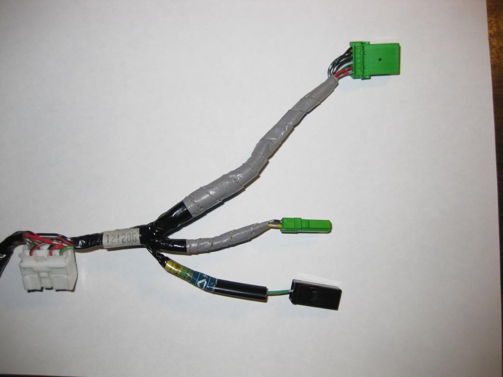
I took my airbag out and and discovered the answers to my questions. My old subharness is labeled 011507 and has three connectors: 1 for horn, 1 for cruise, and 1 white connector. The steering subharness I bought is labeled "121206" and has 7 connectors: 1 white connector that connects to the cable reel, 1 for horn, 1 for cruise (maybe?), 1 for audio controls, 1 for bluetooth controls, and 2 for paddle shifters. I'm not sure about the cruise connector because it doesn't fit the US Sport cruise controls; the US connector is 7pins and the one on the new subharness is 6pins. As pointed out by arteitle, the cruise connector (7 pins) is the same as the audio connector on the new subharness that I bought so you can chop apart a US subharness and use the cruise control connector for the audio buttons to save some money. Also, the new subharness has a different pinout from the one installed on my 2007 manual sport. Just a slight correction to b17gsr, there are 5 open slots for contacts on the white cable reel connector on the 07 sport, not 4 .
I followed the directions from b17gsr, with some modifications. I unwrapped the tape (except the grey tape leading up to the audio and bluetooth connectors) from all the wires of the new steering subharness. I then disconnected the three contacts (common, audio ctrl signal, and bluetooth ctrl signal) from the white connector (as explained by b17gsr). I then noticed that the red and red/black wires were all that kept the audio and bluetooth connectors connected to the new wire subharness; the red and red/black wires went to both the white connector and the cruise connector. Instead of cutting these two wires and then splicing them into the red and red/black wires of the old subharness, I disconnected the contacts from the white connector and then the cruise control connector; simply sticking a jumbo-sized paperclip into the square hole underneath the sockets of the cruise control connector releases the contact from the connector.
Then going back to the old subharness, I removed the red and red/black wires from the white connector and the cruise control connector. I then connected the five contacts (three for controls and the two for backlighting) to the white connector. I then connected the two contacts (for backlighting) to the
cruise control connector. This let me merge the two subharnesses without having to do any splicing or soldering!
The audio controls I ordered came with a bluetooth controls module, which has four buttons. Attaching the bluetooth controls to the audio controls when mounted in the steering wheel required cutting a decent-sized hole in the plastic cowling on the side of the steering wheel. The bluetooth buttons look nice when installed.
I disconnected three unused wires from the new steering subharness and connected them to the white connector found on the other side of the cable reel. I did some resistance checks and turned on the headlights to see both sets of buttons light up, so all is good to go. Now I just have to order a new headunit and the PAC device to begin using the buttons.
First off, 321liftoff did an excellent job describing how to install JDM RADIO/BT/NAVI controls to your stock USDM steering wheel. Since I myself have done this mod, I would like to share as well.
Here is my guide to integrate JDM Radio/BT/Navi controls to your GD3 Honda Fit Sport steering wheel.
(I do not take any responsibility for any damages that occur from using my guide. This is strictly for informational use only.)
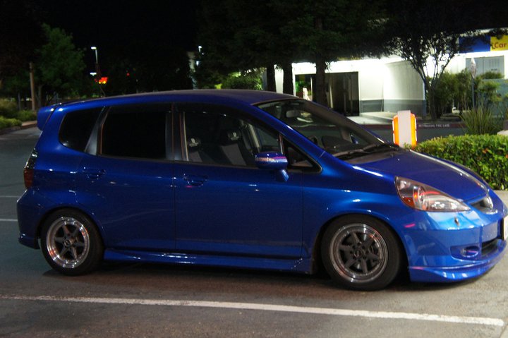
NOTE: You can install these to a NON-Sport model like I did, but it requires you to obtain a stock Sport steering wheel and a stock Sport clockspring. The one I made was put up for sale and has sold. Go here for additional pics.
You will see that I customized the steering wheel harness and created my own harness that comes out the car side of the clockspring where I customized the pin out locations for both. This allowed me to utilize the added Radio/BT/Navi controls, but also use the paddle shifters as momentary on/off buttons and the cruise control on/off button as an on/off button. I only used the paddle shifters to power on the arrow blinkers I had integrated behind the side mirror glass. They only powered on when the designated blinker was actually on and by pressing the corresponding paddle shifter (left or right) it would light up the additional blinker behind the mirror glass by way of grounding the circuit. So in effect I had 3 blinkers on always (front, rear, side mirror housing) with an optional 4th behind the glass! But I digress… Let’s get started with the mod.
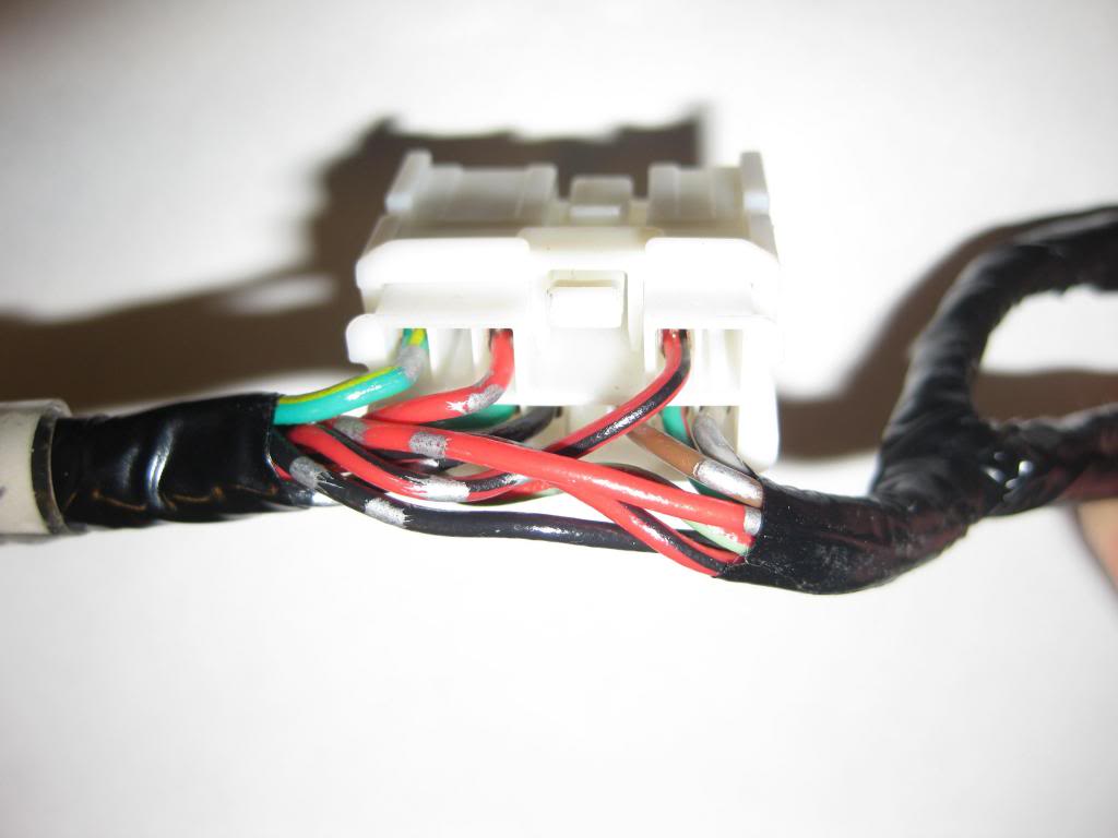
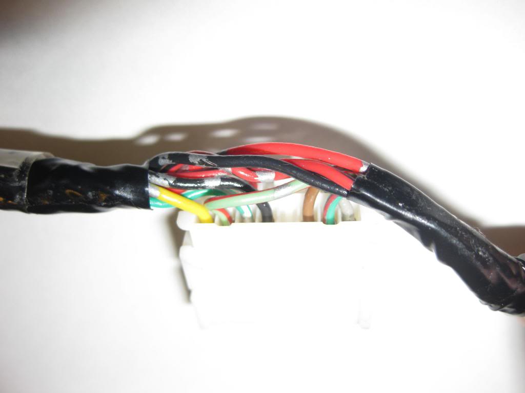
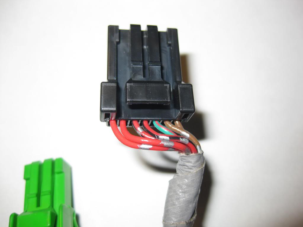
Now some have asked, can you just order the JDM Sport steering wheel harness and swap it out with your USDM Sport steering wheel harness? I would say no based on the fact that there are different colored wires used for the cruise control between the two versions and also the pin location of those wires are not the same. I do have photos of the main harnesses for both JDM and USDM so you can see what I’m talking about.
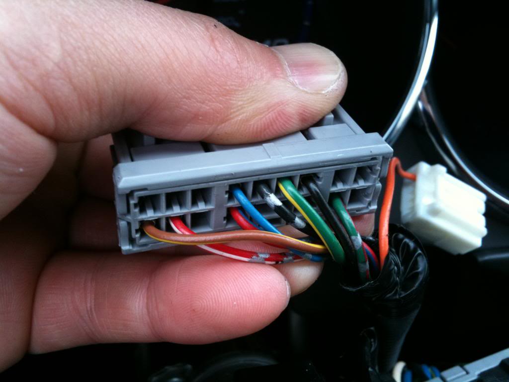
USDM Main Harness (NOTE: This Sport steering wheel harness is for a manual version, thus it does not include wires for the paddle shifters on an Automatic Sport steering wheel. So if you have an Automatic Sport you will likely have a few more wires where I indicate 4 “Blank” pin locations, but I’m positive based on previous post that you should still have 1 or 2 “Blank” pin locations left over.)
On top you have:
Green/Yellow, Blank, Red, CLIP, Red/Black, Blank
On bottom you have:
Blank, Blank, Blank, Blank, Lite Green/Black, Grey/Red, Lite Green, Pink
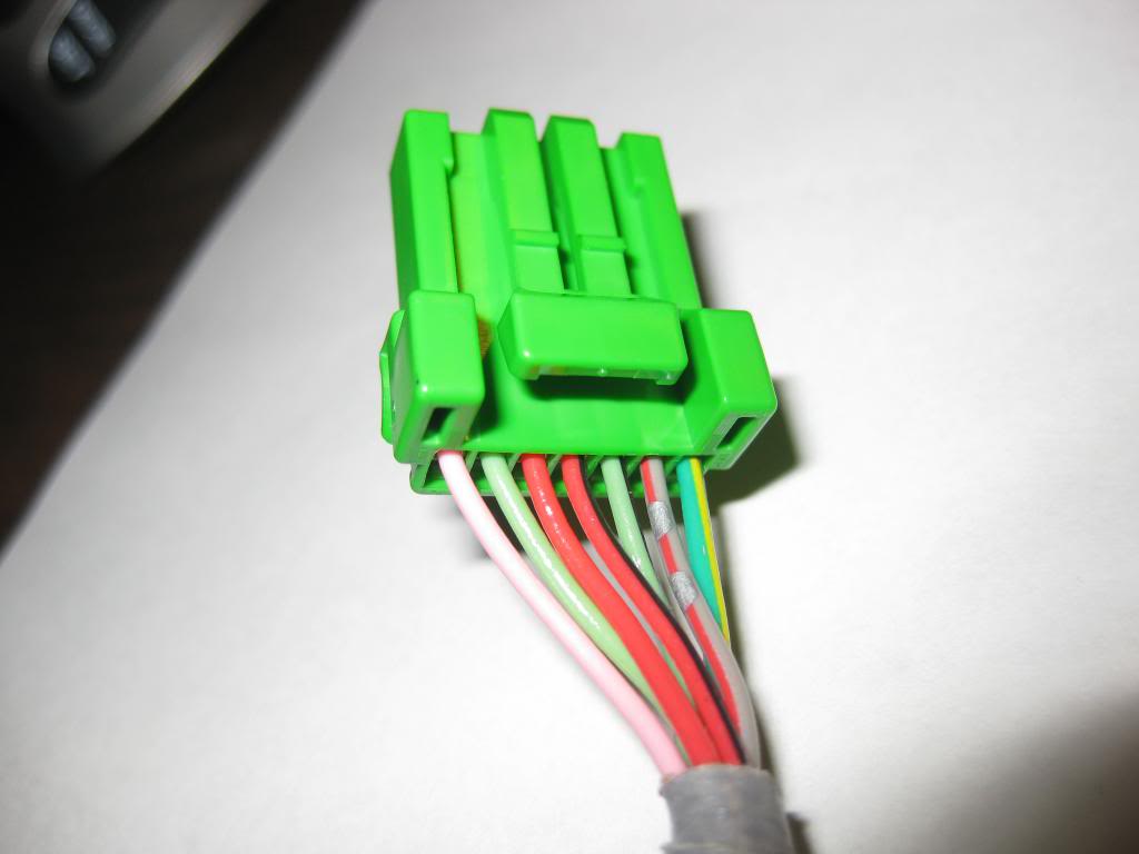
JDM Main Harness
On top you have:
Green/Yellow, Blank, Red, CLIP, Red/Black, Blank
On bottom you have:
Yellow, Lite Green/Red, Green/White, Black, Blank, Brown, Green/Red, Grey
Now what are these wires and what do they do. Here is a key for MOST of them. Obviously the USDM and JDM use different colors for their cruise control and the JDM one includes 3 additional wires.
UDSM Main Harness
On top:
Green/Yellow = Horn
Red = Illumination +
Red/Black = Illumination –
On bottom:
Lite Green/Black = Resume/Accelerate
Grey/Red = Decelerate/Set
Lite Green = Cruise on/off
Pink = Cruise on/off
JDM Main Harness
On top:
Green/Yellow = Horn
Red = Illumination +
Red/Black = Illumination –
On bottom you have:
Yellow = Paddle Shifter +
Lite Green/Red = Paddle Shifter -
Green/White = Unknown Cruise Control Wire
Black = Unknown Cruise Control Wire
Brown = Common Ground - for Radio/BT/Navi Plugs
Green/Red = Audio signal for Radio Plug (Sends out RESISTANCE READINGS)
Grey = BT/NAVI signal for BT/NAVI plug (Sends out RESISTANCE READINGS)
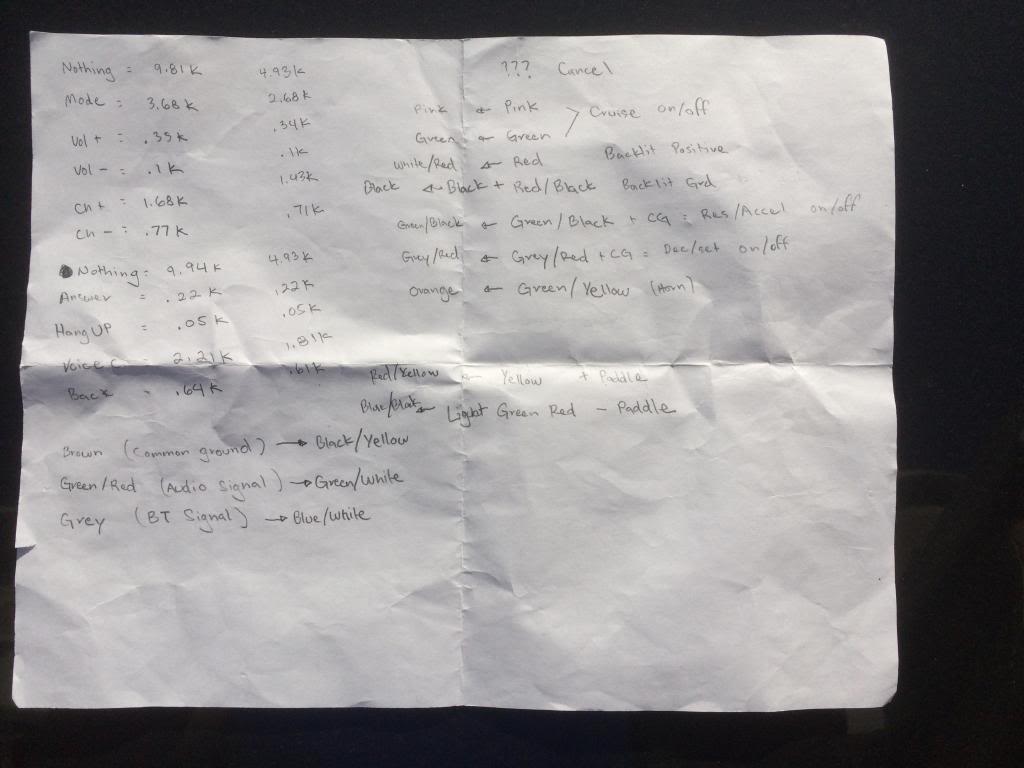
Resistance readings what do I mean? Basically when you press on either of the RADIO/BT/NAVI buttons they send out a different resistance reading for each button. You can get the same readings even if you splice the Green/Red wire with the Grey wire. Here are those readings that I recorded:
On Radio controls:
When NOTHING is pressed = 9.81k ~ 4.93k
When MODE is pressed = 3.68K ~ 2.68K
When VOL + is pressed = .35k ~ .34k
When VOL – is pressed = .1k
When CH + is pressed = 1.68k ~ 1.43k
When CH – is pressed = .77k ~ .71k
On BT/NAVI controls:
When Nothing is pressed = 9.94k ~ 4.93k
When ANSWER is pressed = .22k
When HANG UP is pressed = .05k
When VOICE COMMAND is pressed = 2.21k ~ 1.81k
When BACK is pressed = .64k
Notice all the buttons each have a different resistance reading and/or range. These different resistance readings are what tell the head unit what function to perform. It is my belief that the stock headunit does not do anything when you connect these resistance wires to any of the open pins in the back of the radio. So this will only work with an aftermarket headunit with a PAC unit coupled between. What the PAC unit does is it takes the readings from the resistance wires and converts it to a signal that the aftermarket headunit understands. PAC units are brand specific and car specific on some. You can see more info here:
So ultimately, you want to combine the Green/Red wire (Audio signal for Radio Plug) with the Grey wire (BT/NAVI signal for BT/NAVI plug) to get a single wire that will connect to the PAC unit of your application. Installation instructions of that wire and other wires on the PAC unit can be searched for here:
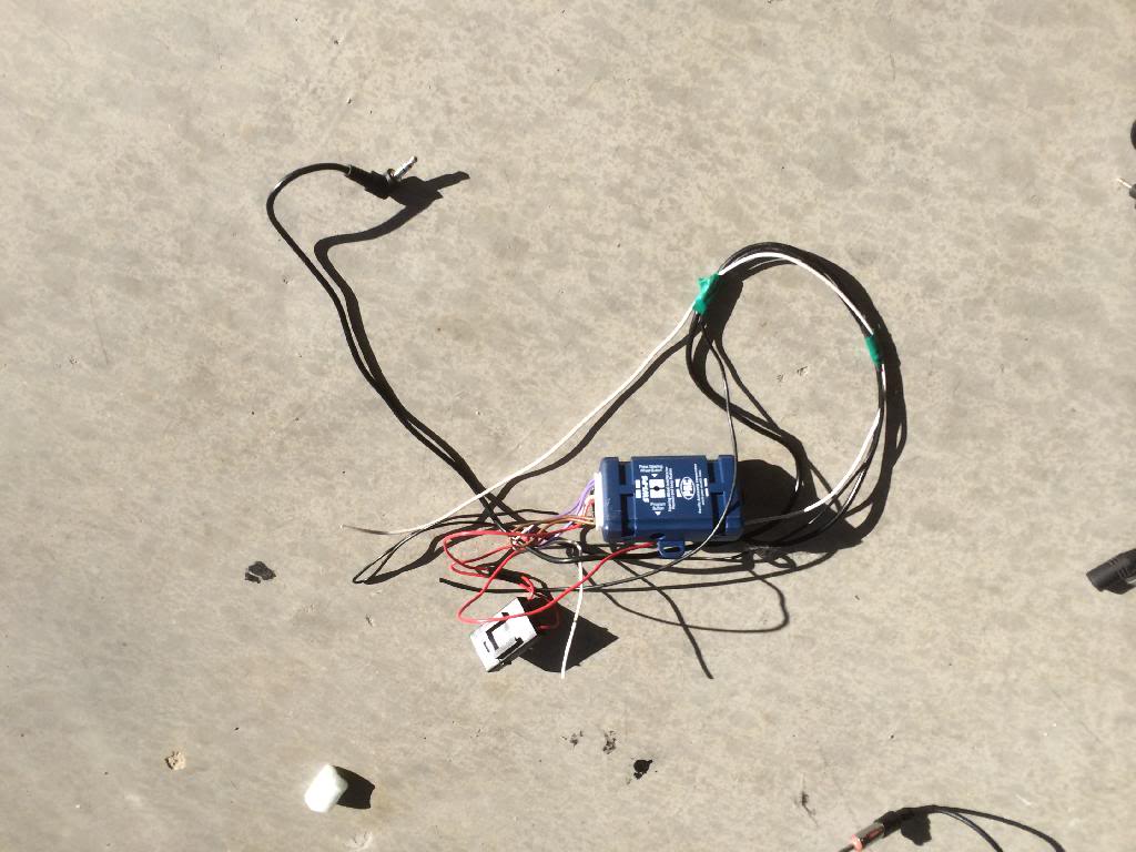
Here is the actual PAC unit I used for my Pioneer deck:
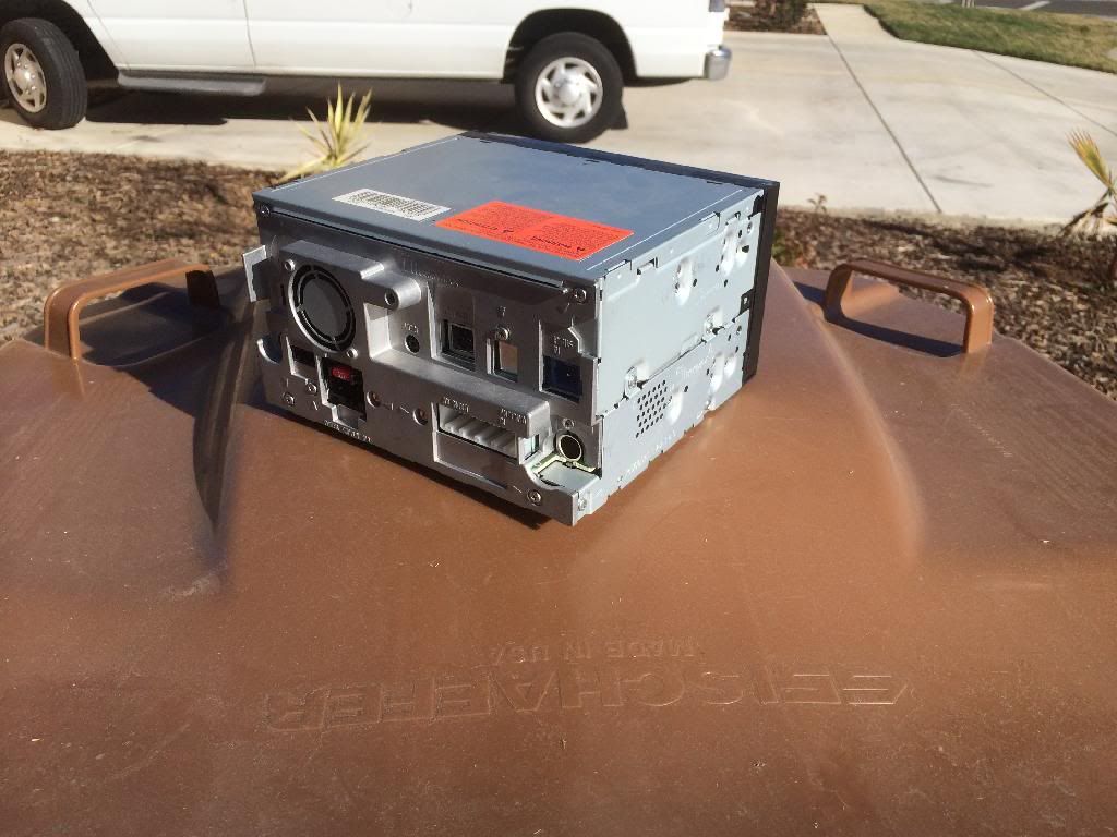
It plugs into the back of the headunit via an earphone jack like plug:
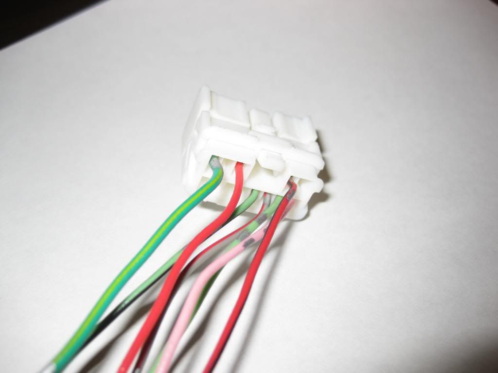
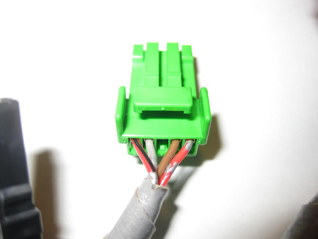
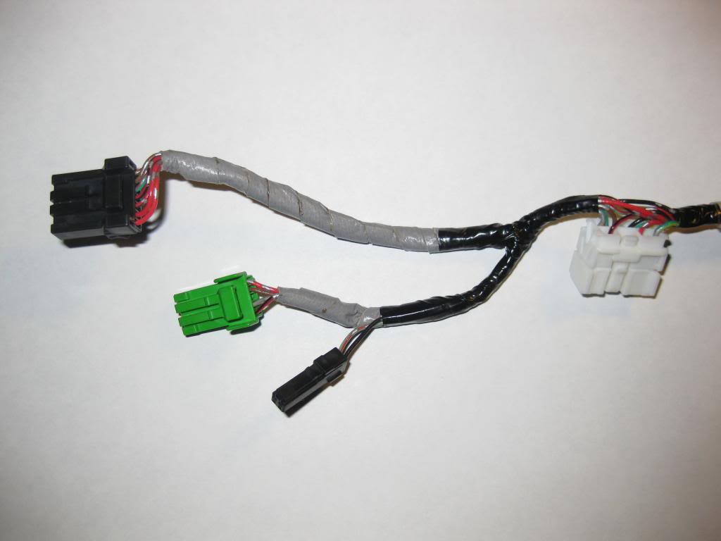
Now back to the physical part of the mod. Basically to modify your steering wheel harness, you will need to unravel the JDM harness and reconnect like wires to your USDM harness. The only ones you will have interest in from the plugs for the RADIO/BT/NAVI controls. That means this group of wires:
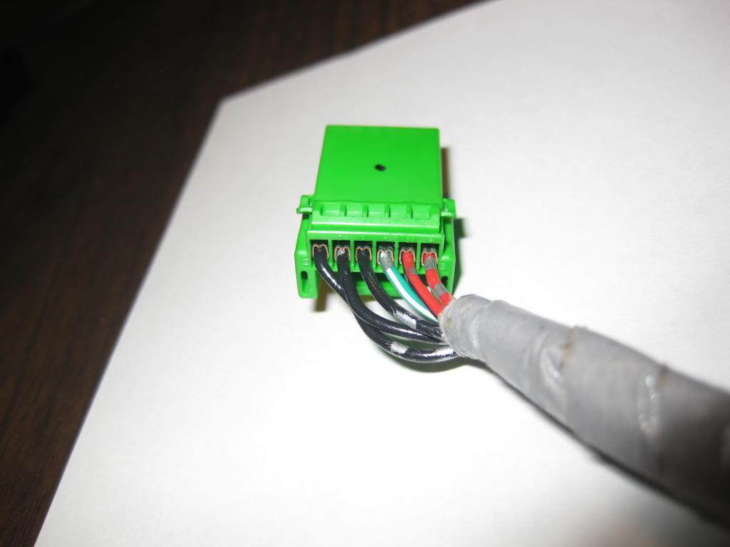
JDM RADIO PLUG:
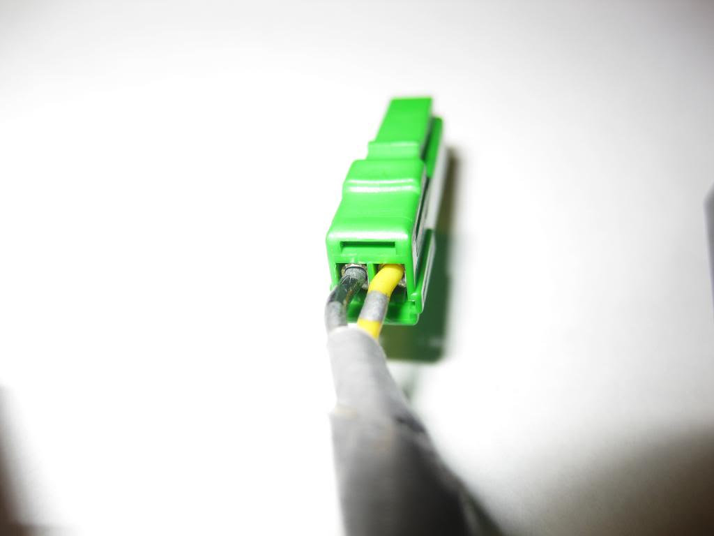
JDM BT/NAVI PLUG:
Wires:
Red = Illumination +
Red/Black = Illumination –
Brown = Common ground –
Green/Red = Audio signal for Radio Plug (Sends out RESISTANCE READINGS)
Grey = BT/NAVI signal for BT/NAVI plug (Sends out RESISTANCE READINGS)
So you should basically connect Red with Red and Red/Black with Red/Black.
321liftoff had an excellent method of taking care of this issue, "I then noticed that the red and red/black wires were all that kept the audio and bluetooth connectors connected to the new wire subharness; the red and red/black wires went to both the white connector and the cruise connector. Instead of cutting these two wires and then splicing them into the red and red/black wires of the old subharness, I disconnected the contacts from the white connector and then the cruise control connector; simply sticking a jumbo-sized paperclip into the square hole underneath the sockets of the cruise control connector releases the contact from the connector. Then going back to the old subharness, I removed the red and red/black wires from the white connector and the cruise control connector. I then connected the five contacts (three for controls and the two for backlighting) to the white connector. I then connected the two contacts (for backlighting) to the cruise control connector. This let me merge the two subharnesses without having to do any splicing or soldering! ."
That leaves you with Brown, Green/Red, and Grey. Depending on how many “Blank” pin locations you have you can combine wires. I would take Green/Red can combine with Grey to have a single wire. Now you have 2 new wires you need to add into your USDM Main Harness. Using the JDM Main Harness for Parts, you can use any 2 wires with their metal pin connector attached to solder onto the ends of first the Brown wire and second the Green/Red & Grey wire so that they can then be plugged into your USDM Main Harness. You will need to add 2 additional wires with their metal pin connector attached to the exit end of this harness on your steering wheel clock spring (located towards the back of the steering wheel column switches i.e. signal and wiper switch mount.) It needs to be placed in the same pin location on the steering wheel side as the exit end. Then you will need to extend those wires and ground what was the BROWN wire and connect the what was GREEN/RED & GREY wire to the PAC unit of your choice.
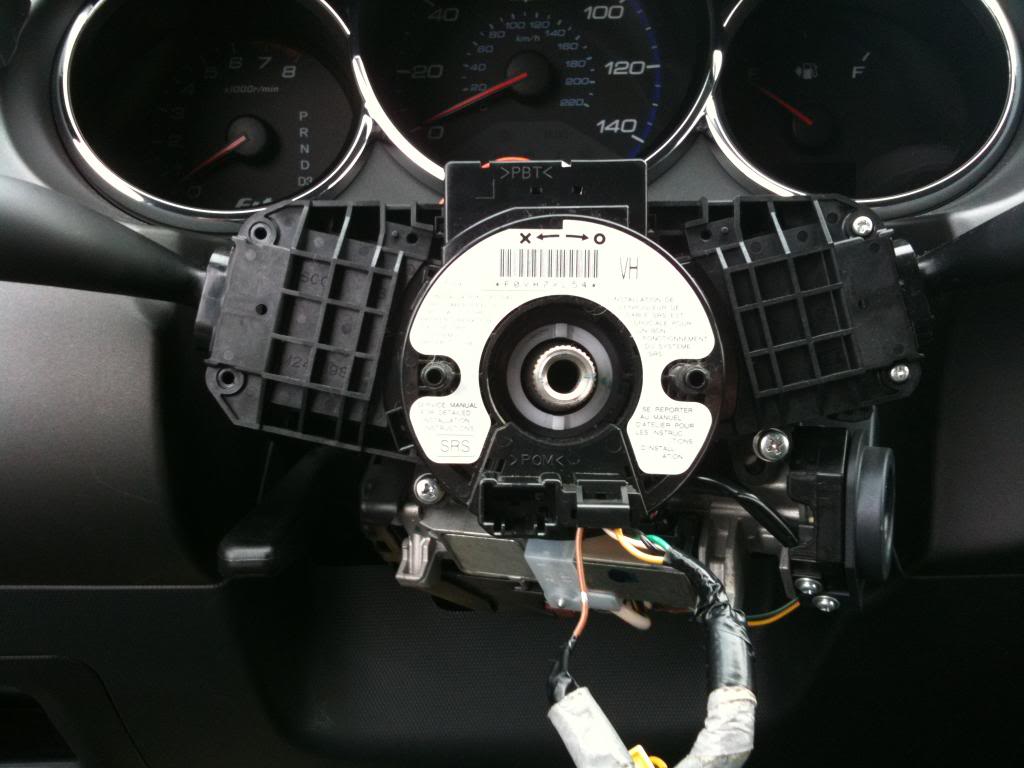
Here is what your steering column looks like with the steering wheel removed. You will see the clockspring located in the center (NOTE: What you see is off my car which had an NON-Sport clock spring. It did not come with a Main Harness like it does for the Sport models instead it comes with a single connector with brown wire attached that plugs into the Horn. The other harness coming out with 4 wires is for the Airbag plug.) To remove the airbag, there are two torx screws on the left and right side behind the steering wheel right about where the paddle shifters are located. Then the airbag plug can be removed from the bottom side, removing a small cover first. Obviously you want to make sure the battery is disconnected before you start messing with anything. The airbag is removed and simultaneously you'll need to unplug the horn wire and you should be free and clear from there to remove the steering wheel via a large nut.
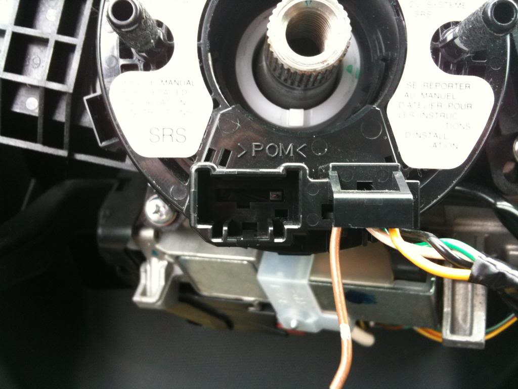
Here’s a top view of the NON-Sport clock spring exit end. You will notice the Airbag plug near the bottom right and to the left of that is where the horn plug plugs into.
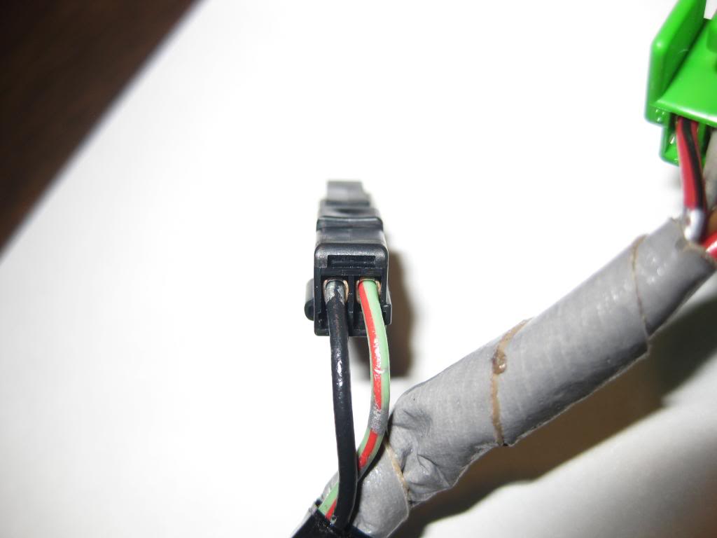
Here’s the horn plug with the orange wire on the exit end. Ignore the plug I’m holding in my hands, that’s for the light switch controls:
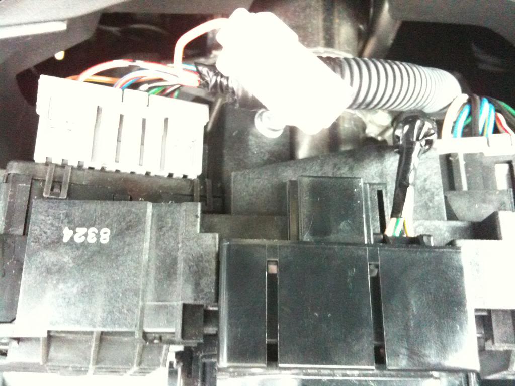
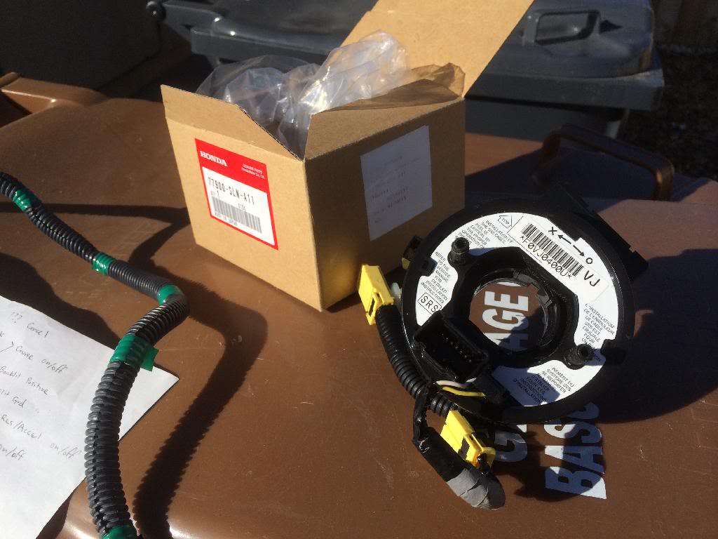
Here is a Sport clock spring. Notice the larger Main Harness plug with plenty of pins:
Now to mount the JDM switches to your USDM steering wheel assembly. The RADIO controls take place of your blank panel. This is easily screwed off. The BT/NAVI controls are also screwed onto the JDM RADIO controls, but it requires you to trim off the back panel of your steering wheel assembly to install. When you take this panel off, you will notice in the plastic a faint outline showing the area of plastic that needs to be removed in order to make room for this added BT/NAVI switch. I’m not positive, but it should be marked on the left and right sides however make sure you cut out the correct side when doing so.
Here are a few extra notes for the two Main Harnesses.
USDM Cruise Control Plug
JDM RADIO Plug
JDM BT/NAVI Plug
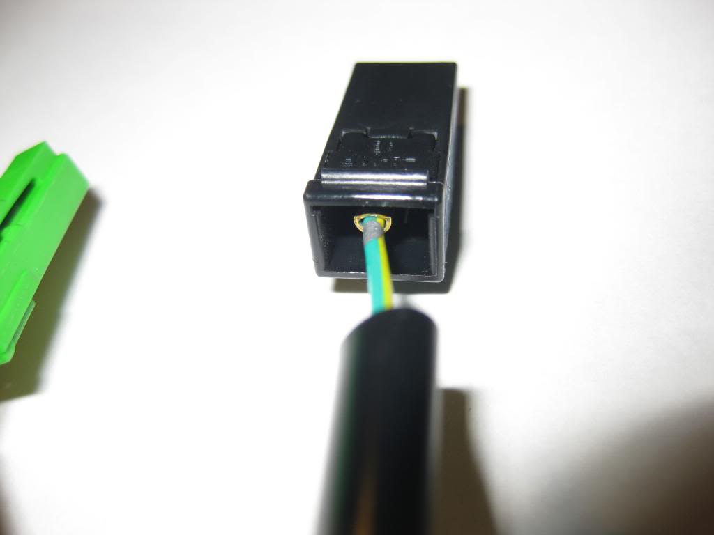
JDM Paddle – Plug
All 3 together:
JDM Cruise Control Plug
JDM Paddle + Plug
JDM Horn Plug
All 3 together:
Hopefully this was an insightful tutorial.
Last edited by Drag0na5h; Jan 27, 2014 at 08:17 PM.
I hope this site isn't a forgotten one. The Post I'm seeing are dated 2016. Well. Anyways I have a 2013 Honda Fit sport with basic factory sound system. I recently purchased an after market double din radio with reverse camera, navigation and onboard steering wheel control, etc. I would like to retain the steering wheel controls for my radio but don't know what wires on the factory harness to hook in to. The new radio harness has the Key1 and Key2 leads that I've read are used for this function. Does anyone know which plug and wires I would tap into for this. I would greatly appreciate any info regarding this. thanks
I hope this site isn't a forgotten one. The Post I'm seeing are dated 2016. Well. Anyways I have a 2013 Honda Fit sport with basic factory sound system. I recently purchased an after market double din radio with reverse camera, navigation and onboard steering wheel control, etc. I would like to retain the steering wheel controls for my radio but don't know what wires on the factory harness to hook in to. The new radio harness has the Key1 and Key2 leads that I've read are used for this function. Does anyone know which plug and wires I would tap into for this. I would greatly appreciate any info regarding this. thanks
You could get an Ohm/Resistance reader and test every single wire in every single harness to see if they give off different resistance readings when you press any of the audio control buttons on your steering wheel. Obviously if you test a wire and it doesn�t do that on one or two tries move on to the next til you find one that does. Then confirm that one (or 2) continue to give off different resistance readings when you press different audio control buttons. That would be my method to locate which wire(s) you need to connect to your Key1 or Key2 leads on your new head unit. I believe if you have one wire you only need to connect to one of those Key wires (either one doesn�t matter). They provide 2 because some cars have a separate control wire for the Navi buttons and another for the Audio buttons. But like my post above one can combine both wires into one and still be able to use it on an aftermarket set up that has only 1 wire for steering controls.
Last edited by Drag0na5h; Apr 9, 2022 at 03:51 PM.
Android head unit wants to add the media control to the steering wheel.
Hi, I recently bought an android head unit 10.1" inch and i want to buy the controller from aliexpress. But I have no idea what to do. Found someone to do it for 200$ but i need the accurate plan for the wirering without interfering with the cruise control.
Do I need to get a premoded clockspring or the wirering is easy to achieve. I know from the video I found over the net wsnt a model with cruise control.
Do I need the pac module or the head unit will recognise the button's so I can make some input config like volume up and long press volume up to change song.
Beside that i installed an dsp amplifier wich raised the 6 speaker ( 145 watts in total to 320 watts)
Backup camera in process, the one i received is not working so i contacted the tec support to get an other one and root my head unit. YT9216CJ_00012_V009 hifi modification in process. So it dsnt drain my battery , and works with bms so I don't stall. Probably will install an odyssey battery 🔋 for the radio and keep the main for the crank start.
Remote starter in a few month (Start-x)
Thx for your help guys that would be much appreciated