
DIY: Rostra cruise control with OEM buttons on base 2007 A/T USDM


Thread Starter
|
Member
Joined: Dec 2010
Posts: 48
From: Michigan, USA

DIY: Rostra cruise control with OEM buttons on base 2007 A/T USDM
DISCLAIMER
Neither I nor fitfreak is responsible for any injury or property damage that could result from this modification. ONLY ATTEMPT THIS AT YOUR OWN RISK. HAVE ALL THE TOOLS NECESSARY TO DO THE JOB PROPERLY. ONLY ATTEMPT IF YOU ARE COMFORTABLE WITH DIY PROJECTS AND HAVE SOME SOLDERING EXPERIENCE. Read everything below before starting on this project.
Introduction
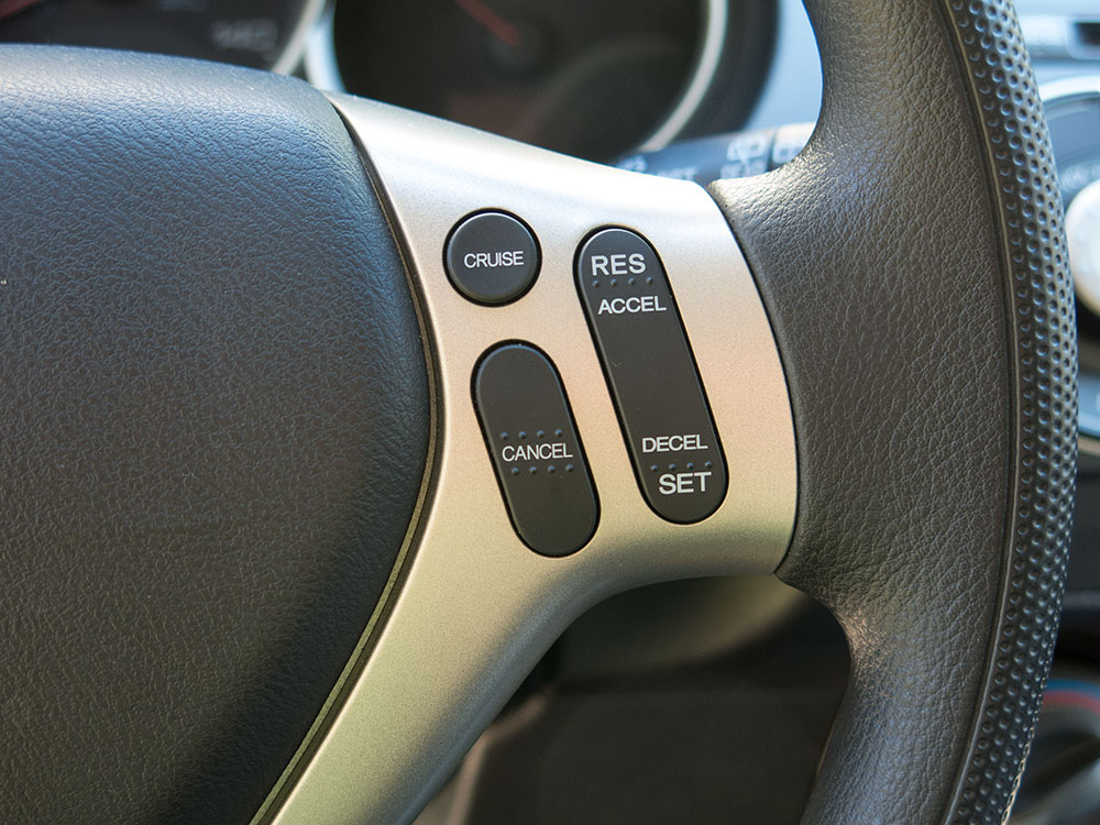
This is a modification that I have been wanting to do for awhile, and I finally got it done!! I have always wanted cruise control, and when I finally decided to install it, I intended to just follow the instructions for the Rostra kit. However, the included dash mount control switch is not very good IMHO. It doesn't look good and doesn't seem very well made. The control stock version Rostra makes seems to be higher quality, but there is no place to install it on the Fit where it is not in the way due to the other control stocks. Thus, I started on the project of making the Rostra kit work with the steering wheel mounted Honda OEM control buttons that are on the sport trim. This is an approach that has been mentioned before in these forums, but to my knowledge, no one has documented doing it. The overview is that you have to install/swap a number of parts from the sport that relate to the cruise buttons. The most significant is that you have to swap the cable reel with the sport one to get enough wires through to the steering wheel.
The structure of this post will be to have the general info and discussion first, then go through the steps to do the mod. What I will be presenting is both the individual steps to do the install and an alternate install design to allow for the use of the OEM buttons. I created this design with the help of the Honda service manual (HSM), the Honda electrical troubleshooting manual (ETM), and the Rostra kit manual. I have proved that it works on the base 2007 A/T USDM, but it might be possible to extend it to all US and Canada GDs. More on this later. I strongly suggest that, if you have the HSM and ETM, you check my work before doing the install. I have confidence in my design, but I want you too as well. Another thing to note is that the airbag wiring is not altered in this modification. The cable reel does need to be swapped with the sport one, but it is another Honda part.
Difficulty
I don't have a lot of experience with car modifications, but I do have a fair amount of soldering experience. Given this, I would consider it to be a very difficult mod. There were times when I thought I should not have started it, but it is one of those projects that, once you have started, you are determined to finish one way or another! Also, I probably made it harder than it needed to be due to some of the design decisions I made. In the steps, I will try to point-out ways that it could be simplified.
Cost
The Rostra kit was $290 and the total of the Honda parts was $288 for a total of $578. This is not counting shipping costs, some special tools needed, and small generic parts needed such as cable zip ties, etc. Also note this was the cost in mid-2013. I have noticed the prices of Honda OEM parts keep going up over time. Obviously, this is a lot of money for cruise control. Whether it is worth it or not is up to you. I got what I wanted out of it, and it was an interesting project to work on.
Design
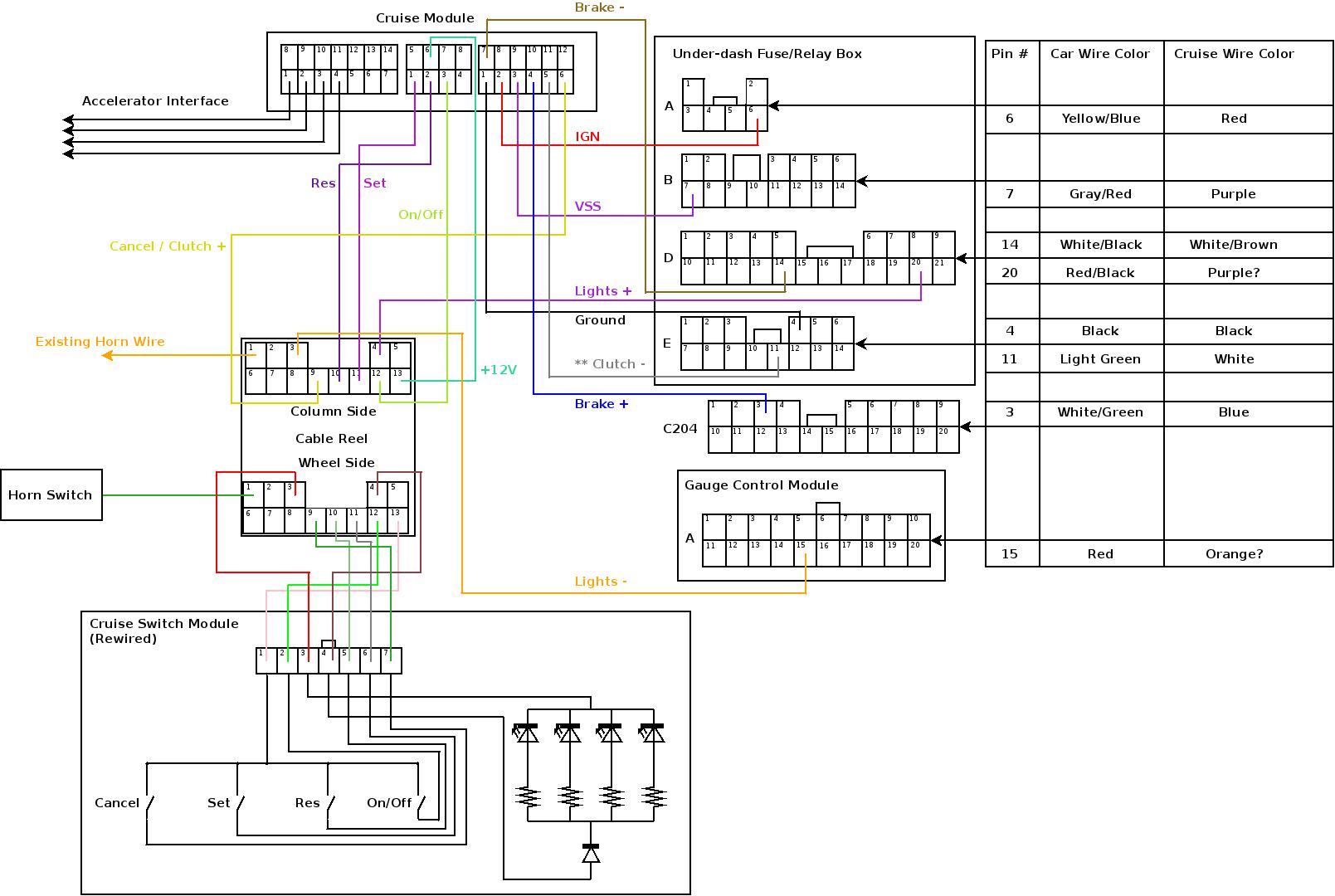
The following diagram will tell you most of what you need to know. It is not to scale and the layout of things is for the convenience of drawing. The connector numbering and view (from the wire side) of the Honda connectors matches the ETM diagrams. The connector numbering and view of the cruise module connectors matches the Rostra manual. The detail of the accelerator interface wiring is not shown since it is plug-and-play.
Some of the main points about the design:
Design applicability to other GDs
Note: This is more or less pure speculation!!
M/T Fits: In the diagram above I have added a connection labeled "** Clutch-" which is not a connection that I actually made. This is the connection that that the Rostra manual shows is necessary for the M/T clutch input with my rerouting to the fuse panel. (From some previous posts in these forums, it seems that the Rostra manual used to be wrong about which clutch input circuit to use. The current revision of the manual seems to have been updated and matches the corrections mentioned in these posts.) I __think__ this is the only alteration that needs to be made for the design to work on M/T GDs. The only reason I have to think that it might not work is that it is not proven that the cruise module can take input from both of its clutch input circuits at the same time. However, since the module doesn't have have an input to check for the presence of a particular clutch circuit (such as it does for the brake circuit), it seems likely that it will work. Obviously, this will have to be experimental for anyone trying it.
2008 Fits: I have older editions of the HSM and ETM that only cover the 2007 models. Thus, I don't know if any of the connections on the fuse panel have moved in the 2008's. It seems unlikely unless the addition of TPMS shifted anything. The same Rostra kit is applicable to 2008 Fits, so it is possible, I just don't know if my design would need to be changed on 2008's. Maybe someone with newer editions of the HSM and ETM can check?
Canadian Fits: The HSM and ETM I have do cover Canadian models, so it should work for them as well with the same caveats above for M/T and 2008.
Parts
Specific parts needed: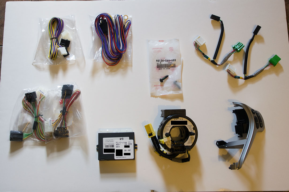
The reason for the two steering wheel sub-wires is that the connector on the back (dash side) of the cable reel is the same as the one on the front (steering wheel side). Rather than buying the dash wiring harness to get the back connector, it is much less costly to get a second steering wheel sub-wire! There are also two versions of this part, one for the sport M/T and one for the A/T. You will at least want to get one of the A/T version because I found that with two of the M/T versions you will be short a pin that is needed. (The A/T version has more pins and connectors for the paddle shifters on the sport.)
The Honda parts can be bought from your favorite online parts store (College Hills / Bernardi / Honda Parts Now / etc.).
Generic parts needed:
Tools
There are many standard tools that are needed such as:
Some less common tools needed:
Tools I don't recommend using:
Time
This project took me a little over a year to complete! I bought the parts in mid-2013 and finished the install in August 2014. My intent was to do this project to the best of my ability, which led to having to rethink my initial thoughts on many things, which made the project longer. There was also winter and moving to another state. If you aren't moving, have a heated garage, and use what I have learned here you might be able to do it faster! But seriously, this project will have to be done in stages. I suggest the following if you want to have a drivable car between each stage:
General installation notes
After some research and the instruction of the Rostra manual, I decided to solder all wiring connections. There is some debate about whether soldering or crimping is better in general. The summary seems to be that crimping is better, but only with very expensive tools and their corresponding crimp connectors. Thus, if you do not have such tools and parts, soldering is still the better option. There is also an "interesting" account here of the results of crimping some of the connections.
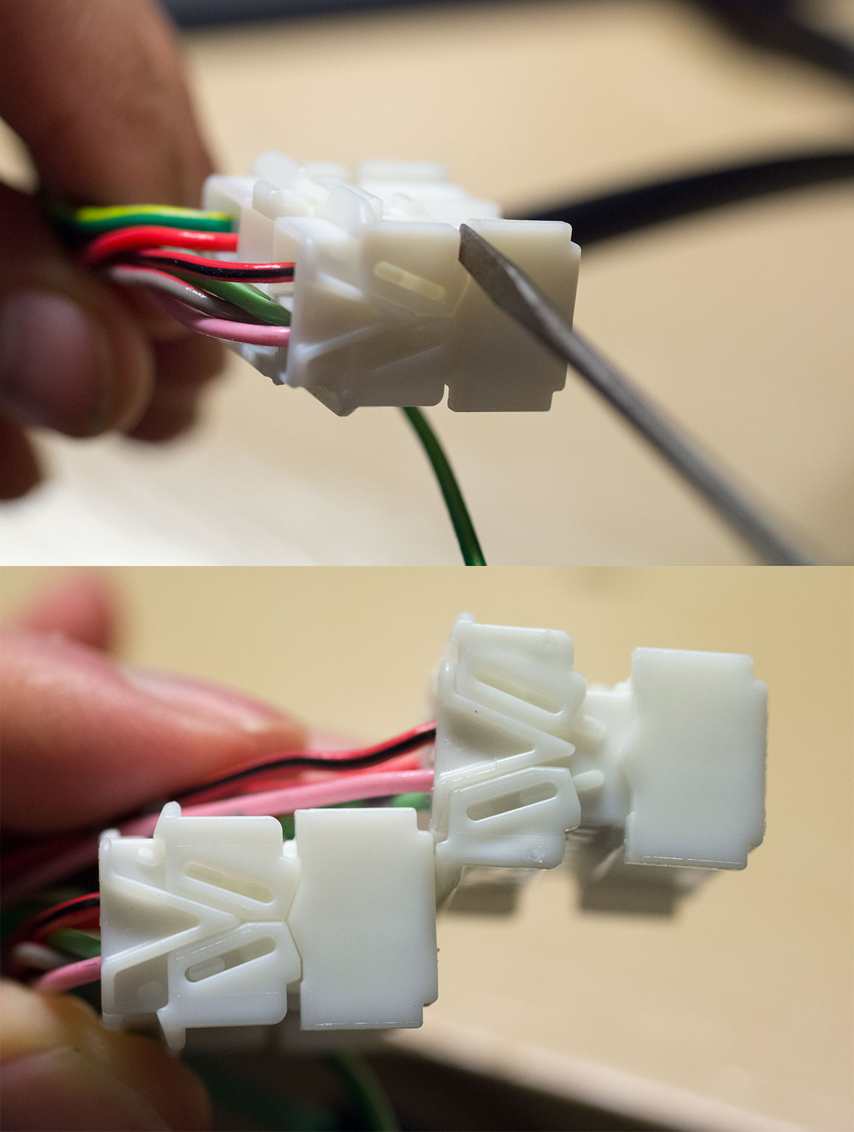
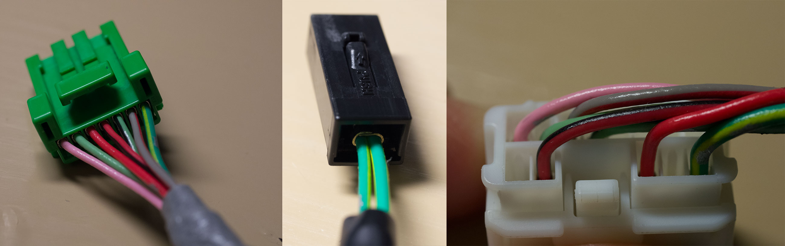
There are two kinds of Honda connectors you will need to be able to disassemble for this project. I don't know if they have real names, but I will call them type A and type B. They both have secondary locks in addition to the clips in them that hold the pins in the connector body.
Type A is pictured below showing how to open the secondary locks with a small screwdriver. Twist the screwdriver on each end to pop the locks open.
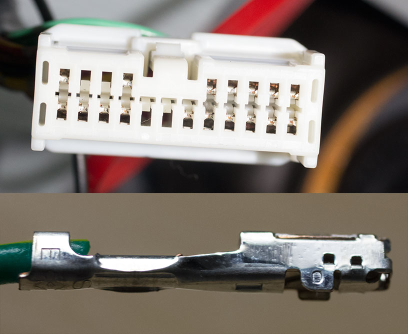
Below is a picture of the pin end of the type A connector. On the middle side of the pins you can see the plastic pins that need to be pushed toward the middle to release the pins from the connector housing. Once these clips have released the pins, the pins can be pulled out the back on the connector housing. It sounds simple but is very difficult. I think it might be easier on newer connectors, and it is easier to do at the bench than in the car. The Honda pin tool set is supposed to help with this task, but fails badly. A large safety-pin is the only tool that gives you a chance at it honestly!
Type B is pictured below. It is much easier to work with than type A. You push the secondary locks down towards the pin-end of the connector slightly and then pull them out towards the sides. I recommend using the plastic opener tools that I mentioned in the specific tools section. After opening the secondary locks they have a pin clip similar to type A if I remember correctly.
This is also the picture for the gauge module connection mentioned below.
Rewiring the buttons
The place to start is rewiring the OEM buttons to separate the cancel button circuit.
Rewire the steering wheel sub-wire
The next stage is to rewire the sub-wire that goes in the steering wheel to separate the new cancel circuit on its own pin to the cable reel. If you choose to buy one M/T version and one A/T version of the sub-wire, I suggest using the M/T version in the steering wheel and cannibalizing the A/T version to get the connector for the dash side of the cable reel. You will need one extra pin from the A/T version to add to the M/T version for the cancel circuit. There are plenty of extras in the A/T version, so it will not be an issue. Obviously, if you are interested in adding other steering wheel mounted controls you will need more pins, and you might need a third sub-wire to steal pins from.
Making the cruise wiring harnesses
The Rostra kit comes with three wiring harnesses:
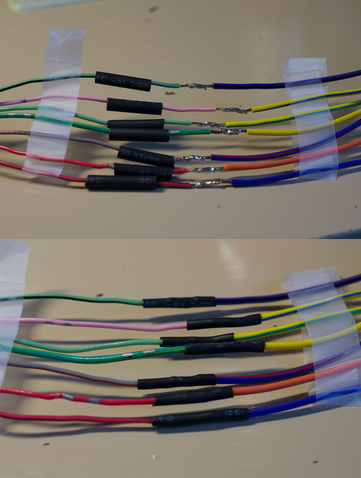
Because of the lights circuits and the cancel circuit, the main and control harnesses end-up becoming one really. See the following overview of the finished harnesses:
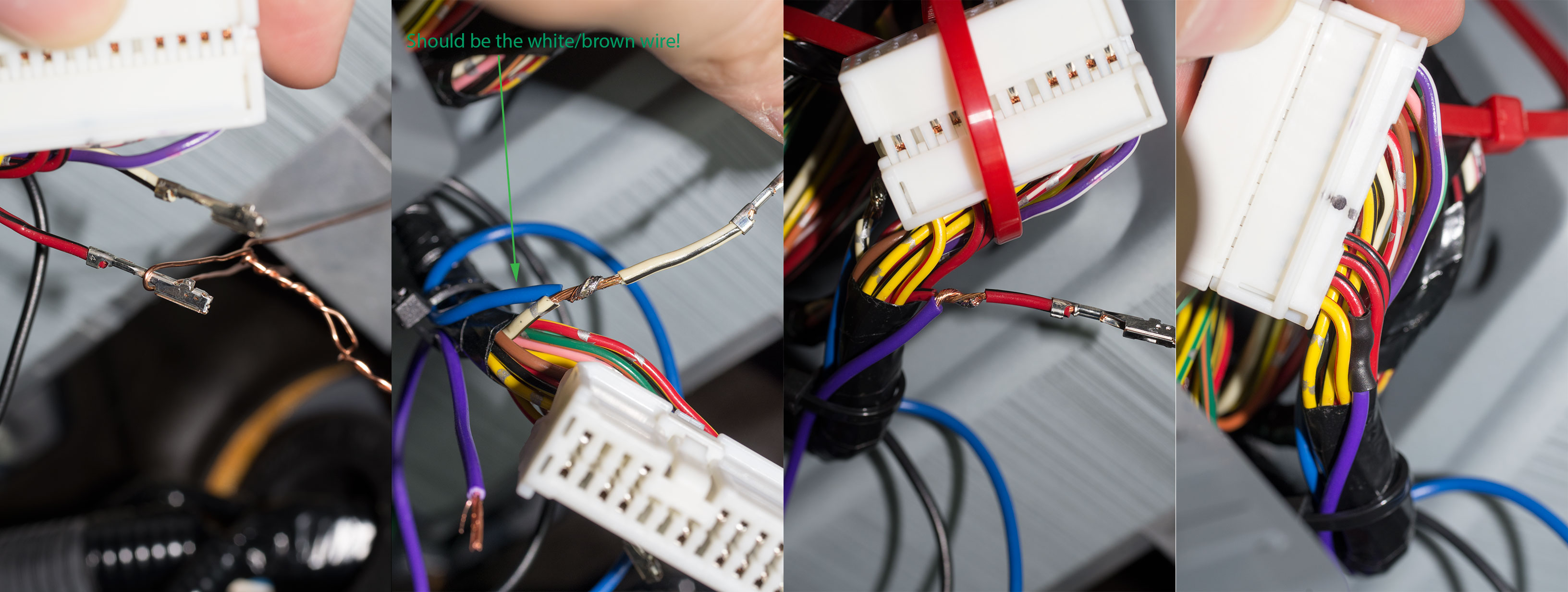
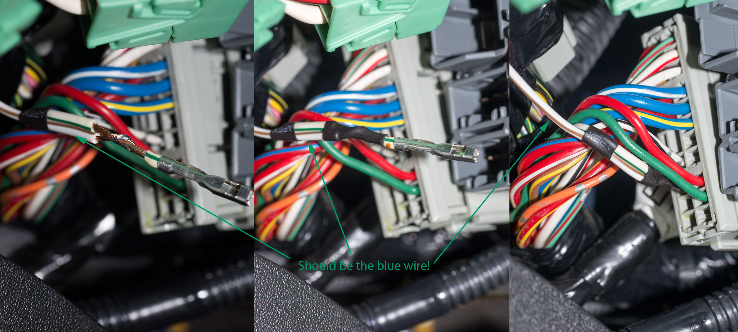
On top is the main harness. In the middle is the control harness. On the bottom is the accelerator harness. The mid-way break-out on the main harness is for the back side connections for the fuse panel. The mid-way break-out on the control harness is for the lights- connection to the gauge module. The total length of the control harness is its length from the kit plus a few inches from the cannibalized sub-wire for the back of the cable reel. One thing to note is that you will need extra wires to use for the lights+ and lights- circuits. I used extra wires from the kit itself. There are a number of unused wires on the main harness that you will want to cut off that can be used. In addition, the VSS wire is about 3 times longer than the others on the main harness. I cut it short to match the length of the others and used the extra for the lights+ circuit. The way I laid it out, the lights+ wire ends-up being one of the longer ones since it has to come back from the control harness, then into the main harness to get to the back of the fuse panel. Below is a before and after picture of the control and main harness connectors to the cruise module (and the accelerator after):
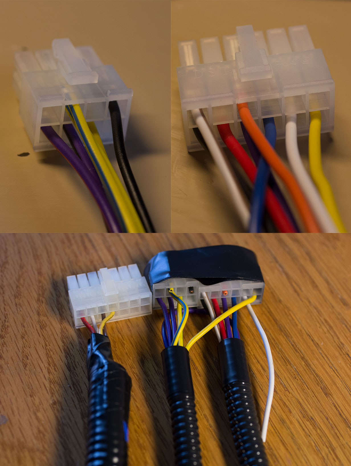
Note the wires that I cut off. These are not used. However, if you are trying on the M/T, you will want to have the white wire included in the main harness. I left a bit of length on it just in case I was wrong about which clutch circuit to use for the cancel! Also note the yellow wire for the cancel jumping over to the control harness and the lights+ purple wire going between the two as well.
On the other end of the control harness you will want to remove the connectors from the kit and splice in the cannibalized sub-wire connector for the back of the cable reel. Again you can choose to put the circuits on any pin you want as they go though the cable reel as long as they match on both sides, and you get the circuits from the main diagram working. However, it makes sense to use their default locations and just add the cancel circuit.
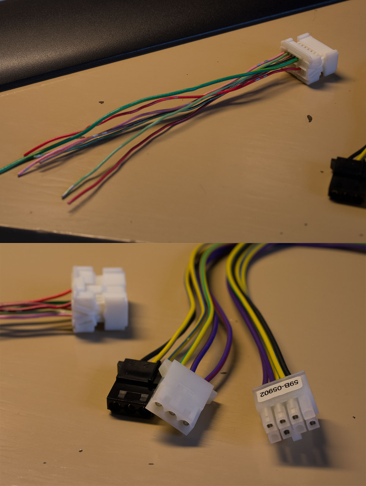
For reference this is the accelerator harness that you want to use:
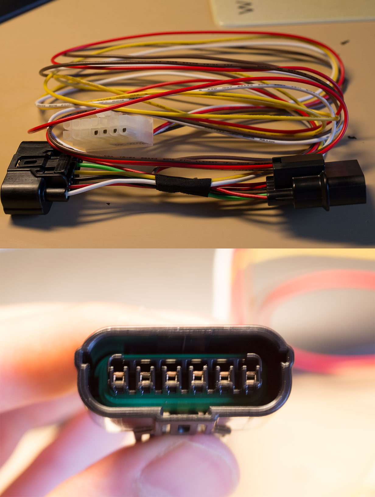
The kit I received had two different accelerator harnesses in it. You want the one with the larger connectors.
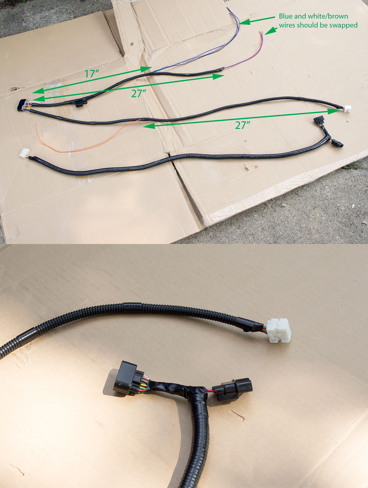
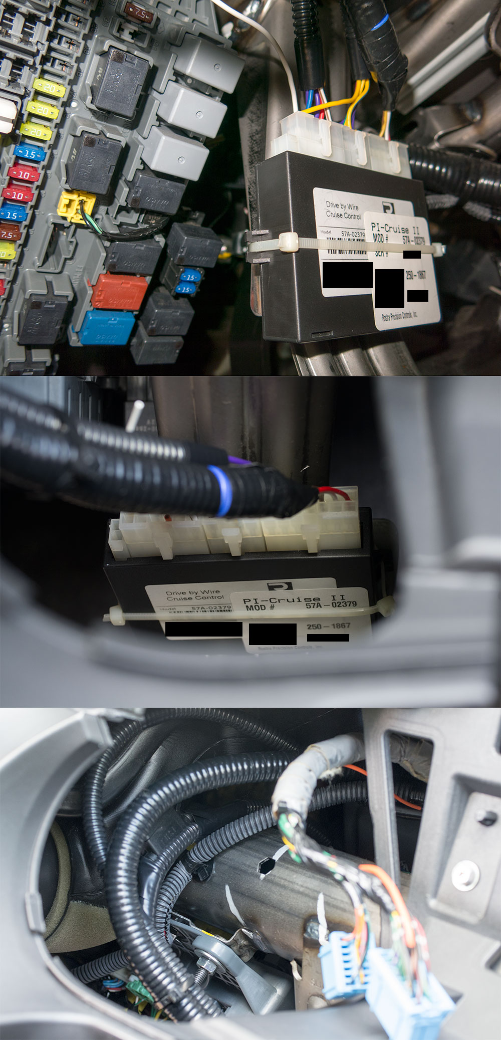
These harness lengths allow for the cruise module to be located to the right of the fuse panel as shown with the harnesses routed over the hanger bar above:
This was the best place I could find for it.
Steering wheel work
The next stage of work is the first on the car itself. The steering wheel needs to be removed and the cable reel swapped. Also the cruise buttons and the modified sub-wire need to be installed into the steering wheel.
Gauge module and wiring work
The next stage is to remove the gauge module and do much of the general wiring work.
Fuse panel wiring connections
There are 6 connections that need to be made around the fuse panel, 3 on the front and 3 on the back. The following picture gives the locations of the front side connectors we are interested in. This is a post modification picture and the arrows indicate the routing of the main harness.
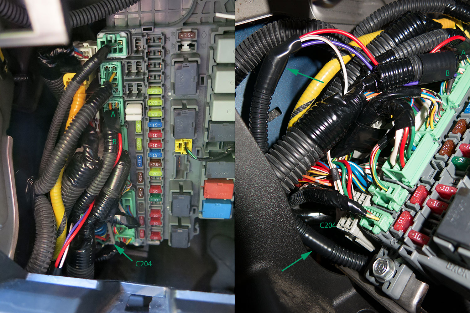
The next picture shows the back connectors we are interested in. Also note the break-out from the main harness for the back connection wires.
Another picture of the back connectors:
Something that will really help with working on the back connectors is detaching the two fuse blocks on the end of the fuse panel. There is a tab (shown below) that releases them and they can be pulled forward and detach from the fuse panel. They can then be pushed to the side to allow better access to the back of the fuse panel.
Connect the accelerator interface cable
Neither I nor fitfreak is responsible for any injury or property damage that could result from this modification. ONLY ATTEMPT THIS AT YOUR OWN RISK. HAVE ALL THE TOOLS NECESSARY TO DO THE JOB PROPERLY. ONLY ATTEMPT IF YOU ARE COMFORTABLE WITH DIY PROJECTS AND HAVE SOME SOLDERING EXPERIENCE. Read everything below before starting on this project.
Introduction
This is a modification that I have been wanting to do for awhile, and I finally got it done!! I have always wanted cruise control, and when I finally decided to install it, I intended to just follow the instructions for the Rostra kit. However, the included dash mount control switch is not very good IMHO. It doesn't look good and doesn't seem very well made. The control stock version Rostra makes seems to be higher quality, but there is no place to install it on the Fit where it is not in the way due to the other control stocks. Thus, I started on the project of making the Rostra kit work with the steering wheel mounted Honda OEM control buttons that are on the sport trim. This is an approach that has been mentioned before in these forums, but to my knowledge, no one has documented doing it. The overview is that you have to install/swap a number of parts from the sport that relate to the cruise buttons. The most significant is that you have to swap the cable reel with the sport one to get enough wires through to the steering wheel.
The structure of this post will be to have the general info and discussion first, then go through the steps to do the mod. What I will be presenting is both the individual steps to do the install and an alternate install design to allow for the use of the OEM buttons. I created this design with the help of the Honda service manual (HSM), the Honda electrical troubleshooting manual (ETM), and the Rostra kit manual. I have proved that it works on the base 2007 A/T USDM, but it might be possible to extend it to all US and Canada GDs. More on this later. I strongly suggest that, if you have the HSM and ETM, you check my work before doing the install. I have confidence in my design, but I want you too as well.
Another thing to note is that the airbag wiring is not altered in this modification. The cable reel does need to be swapped with the sport one, but it is another Honda part.Difficulty
I don't have a lot of experience with car modifications, but I do have a fair amount of soldering experience. Given this, I would consider it to be a very difficult mod. There were times when I thought I should not have started it, but it is one of those projects that, once you have started, you are determined to finish one way or another!
Also, I probably made it harder than it needed to be due to some of the design decisions I made. In the steps, I will try to point-out ways that it could be simplified.Cost
The Rostra kit was $290 and the total of the Honda parts was $288 for a total of $578. This is not counting shipping costs, some special tools needed, and small generic parts needed such as cable zip ties, etc. Also note this was the cost in mid-2013. I have noticed the prices of Honda OEM parts keep going up over time. Obviously, this is a lot of money for cruise control. Whether it is worth it or not is up to you. I got what I wanted out of it, and it was an interesting project to work on.
Design
The following diagram will tell you most of what you need to know. It is not to scale and the layout of things is for the convenience of drawing. The connector numbering and view (from the wire side) of the Honda connectors matches the ETM diagrams. The connector numbering and view of the cruise module connectors matches the Rostra manual. The detail of the accelerator interface wiring is not shown since it is plug-and-play.
Some of the main points about the design:
- No OEM wires were cut in the making of this mod.
- The OEM buttons have to be rewired to work with the cruise module. The cancel button circuit has to be separated from the set and resume button circuits. Luckily, there is an extra pin on the button board that is used in an odd way in the OEM circuit. I don't fully understand the OEM circuit, but it seems that one of its design goals was to minimize the number of wires in the cable reel. What we are doing is expanding these circuits to separate the buttons from each other and the horn.
- One of the clutch input circuits on the cruise module can be used for the cancel button. The clutch press and the cancel press have the same behavior which is why it works. It is also worth noting at this point that there are two clutch input circuits on the cruise module. One is triggered by being connected to the + side and the other is triggered by being connected to the - side. We are using the + triggered one for the cancel.
- The cruise button lights are wired to the same circuits that they are on the sport, thus they work the same as they do on the sport (on/off/dimming with the rest of the dash lights).
- I used the ETM to trace many of the connection points given in the Rostra manual back to the under-dash fuse panel to consolidate the wiring there. This is of dubious benefit. I did this in an attempt to simplify things, but I think I may have made it harder. It is harder because you have to deal with more Honda connectors which are a big pain to work with. The other assumption that I make is that you will be removing the connector pins from the connector housings to make the connections. It may be possible to make the connections without doing this, although the insulation will have to be done differently than I did it. If you want to avoid the fuse panel as much as possible, you should use the connection points in the Rostra manual for the brake+, brake-, and ground connections.
- I made one mistake in my initial design which was swapping the brake+ and brake- due to the brake switch connector numbers not matching between the ETM and the Rostra manual. I have corrected the diagram shown here, but some of the pics later show the wrong wire colors being used. I have made notes in the relevant pics. (It is worth noting that my design and the ETM primarily use pin location/number to identify connections while the Rostra manual primarily uses wire color to identify connections.)
Design applicability to other GDs
Note: This is more or less pure speculation!!
M/T Fits: In the diagram above I have added a connection labeled "** Clutch-" which is not a connection that I actually made. This is the connection that that the Rostra manual shows is necessary for the M/T clutch input with my rerouting to the fuse panel. (From some previous posts in these forums, it seems that the Rostra manual used to be wrong about which clutch input circuit to use. The current revision of the manual seems to have been updated and matches the corrections mentioned in these posts.) I __think__ this is the only alteration that needs to be made for the design to work on M/T GDs. The only reason I have to think that it might not work is that it is not proven that the cruise module can take input from both of its clutch input circuits at the same time. However, since the module doesn't have have an input to check for the presence of a particular clutch circuit (such as it does for the brake circuit), it seems likely that it will work. Obviously, this will have to be experimental for anyone trying it.
2008 Fits: I have older editions of the HSM and ETM that only cover the 2007 models. Thus, I don't know if any of the connections on the fuse panel have moved in the 2008's. It seems unlikely unless the addition of TPMS shifted anything. The same Rostra kit is applicable to 2008 Fits, so it is possible, I just don't know if my design would need to be changed on 2008's. Maybe someone with newer editions of the HSM and ETM can check?
Canadian Fits: The HSM and ETM I have do cover Canadian models, so it should work for them as well with the same caveats above for M/T and 2008.
Parts
Specific parts needed:
- The Rostra kit (part # 250-1867 at M&R Electronics)
- Cruise button module - Honda part # 36770-SLN-A01
- Sport cable reel - Honda part # 77900-SLN-A11
- Steering wheel sub-wire - 2x Honda part # 77901-SLN-A00 (M/T) or 77901-SLN-A10 (A/T)
- Airbag bolt - 2x Honda part # 90134-S6A-A80 (The HSM instructs the replacement of the airbag bolts whenever the airbag is removed.)
The reason for the two steering wheel sub-wires is that the connector on the back (dash side) of the cable reel is the same as the one on the front (steering wheel side). Rather than buying the dash wiring harness to get the back connector, it is much less costly to get a second steering wheel sub-wire!
There are also two versions of this part, one for the sport M/T and one for the A/T. You will at least want to get one of the A/T version because I found that with two of the M/T versions you will be short a pin that is needed. (The A/T version has more pins and connectors for the paddle shifters on the sport.)The Honda parts can be bought from your favorite online parts store (College Hills / Bernardi / Honda Parts Now / etc.).
Generic parts needed:
- About 15' of 1/4" diameter split-loom wire tubing (I found that anything over 1/4" was too big to route where I wanted.)
- Cable zip ties of various sizes
- Electrical tape
- Solder (preferably both lead-free and lead solder to be used in different places)
- Desoldering braid
- 30-gauge varnished wire (magnet wire)
- Heat-shrink tubing
Tools
There are many standard tools that are needed such as:
- All kinds of screwdrivers, mostly smaller ones
- Needle-nose pliers of various sizes
- Tweezers of various sizes
- A wire stripper
- A utility knife
- Side cutters
- Your favorite soldering kit
- A socket set
Some less common tools needed:
- A socket drive toque wrench (for airbag and steering wheel reassembly)
- A socket drive Torx T30 bit (for airbag bolts)
- Plastic opening tools or similar (for opening Honda connectors)
- A heavy-duty "spudger" or similar (for opening Honda connectors)
- A large safety-pin (for opening Honda connectors)
- A small milling/grinding tool such as a Dremel tool (for work needed on the OEM buttons)
Tools I don't recommend using:
- The Honda pin toolset (completely useless, a large safety-pin is much better!)
Time
This project took me a little over a year to complete! I bought the parts in mid-2013 and finished the install in August 2014. My intent was to do this project to the best of my ability, which led to having to rethink my initial thoughts on many things, which made the project longer. There was also winter and moving to another state. If you aren't moving, have a heated garage, and use what I have learned here you might be able to do it faster!
But seriously, this project will have to be done in stages. I suggest the following if you want to have a drivable car between each stage:- Rewire the OEM buttons. (Bench work)
- Make the cruise wiring parts. (Bench work)
- Pull the steering wheel, swap the cable reel, install the OEM buttons and steering wheel wiring, and reinstall the steering wheel. Garage work doable in a weekend of car downtime.
- Remove the gauge module, put the cruise module in place, route the wiring, make the one connection needed on the gauge module connector, and reinstall the gauge module. Garage work doable in a weekend of car downtime.
- Make the remaining wiring connections. If you do it the way I did, this is likely to be multiple weekends of work due to the difficulty of working with the Honda connectors. Because all of the soldered connections are inputs to the cruise module, it doesn't matter if only some of them are done, the car will still be drivable. Just don't connect the accelerator interface cable!
- Connect the accelerator interface cable. At this point the cruise module will actually be in the circuit, and you should have it working!
General installation notes
After some research and the instruction of the Rostra manual, I decided to solder all wiring connections. There is some debate about whether soldering or crimping is better in general. The summary seems to be that crimping is better, but only with very expensive tools and their corresponding crimp connectors. Thus, if you do not have such tools and parts, soldering is still the better option. There is also an "interesting" account here of the results of crimping some of the connections.
There are two kinds of Honda connectors you will need to be able to disassemble for this project. I don't know if they have real names, but I will call them type A and type B. They both have secondary locks in addition to the clips in them that hold the pins in the connector body.
Type A is pictured below showing how to open the secondary locks with a small screwdriver. Twist the screwdriver on each end to pop the locks open.
Below is a picture of the pin end of the type A connector. On the middle side of the pins you can see the plastic pins that need to be pushed toward the middle to release the pins from the connector housing. Once these clips have released the pins, the pins can be pulled out the back on the connector housing. It sounds simple but is very difficult. I think it might be easier on newer connectors, and it is easier to do at the bench than in the car. The Honda pin tool set is supposed to help with this task, but fails badly. A large safety-pin is the only tool that gives you a chance at it honestly!
Type B is pictured below. It is much easier to work with than type A. You push the secondary locks down towards the pin-end of the connector slightly and then pull them out towards the sides. I recommend using the plastic opener tools that I mentioned in the specific tools section. After opening the secondary locks they have a pin clip similar to type A if I remember correctly.
This is also the picture for the gauge module connection mentioned below.
Rewiring the buttons
The place to start is rewiring the OEM buttons to separate the cancel button circuit.
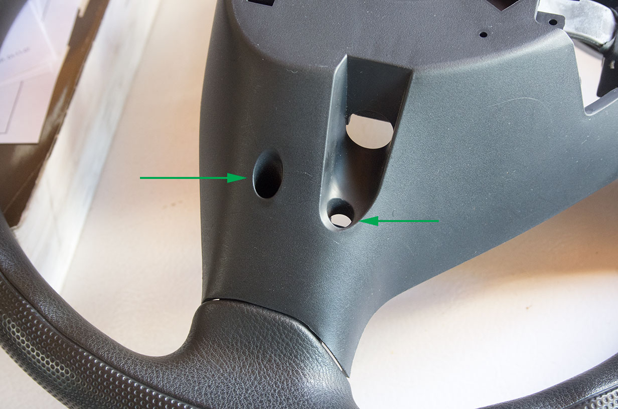
- First remove the switch module from the trim panel that it is attached to by removing the screws.
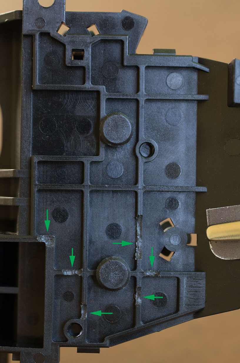
- Use a small screwdriver to release the tabs shown below to open the housing.
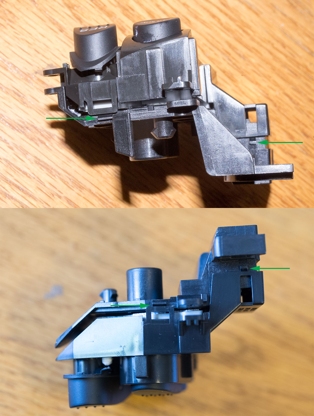
- Note how the parts of the switch module go back together.
- See the following pictures of how the switch board needs to be altered. I recommend using the lead-free solder for the work on the switch board since it is likely lead-free solder that is already on it.
Top:
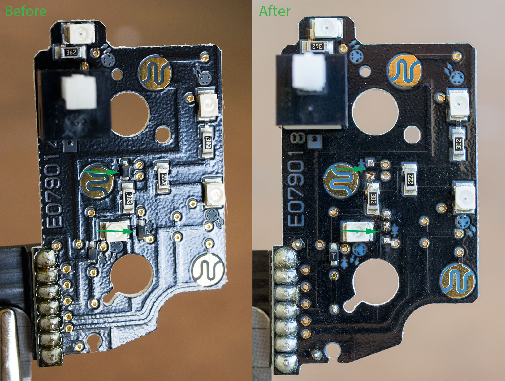
Bottom:
- Removing the two diodes at the arrows on the top of the board separates the cancel button from the set and res circuits. I de-soldered them from the board, but this was very difficult, and it might be easier to use the milling (Dremel) tool to grind them away.
- Note the cut trace at the arrow on the bottom of the board. I also did this with the milling tool.
- The ends of the varnished wire will need to be de-varnished with a knife or fine sandpaper before soldering them into the holes.
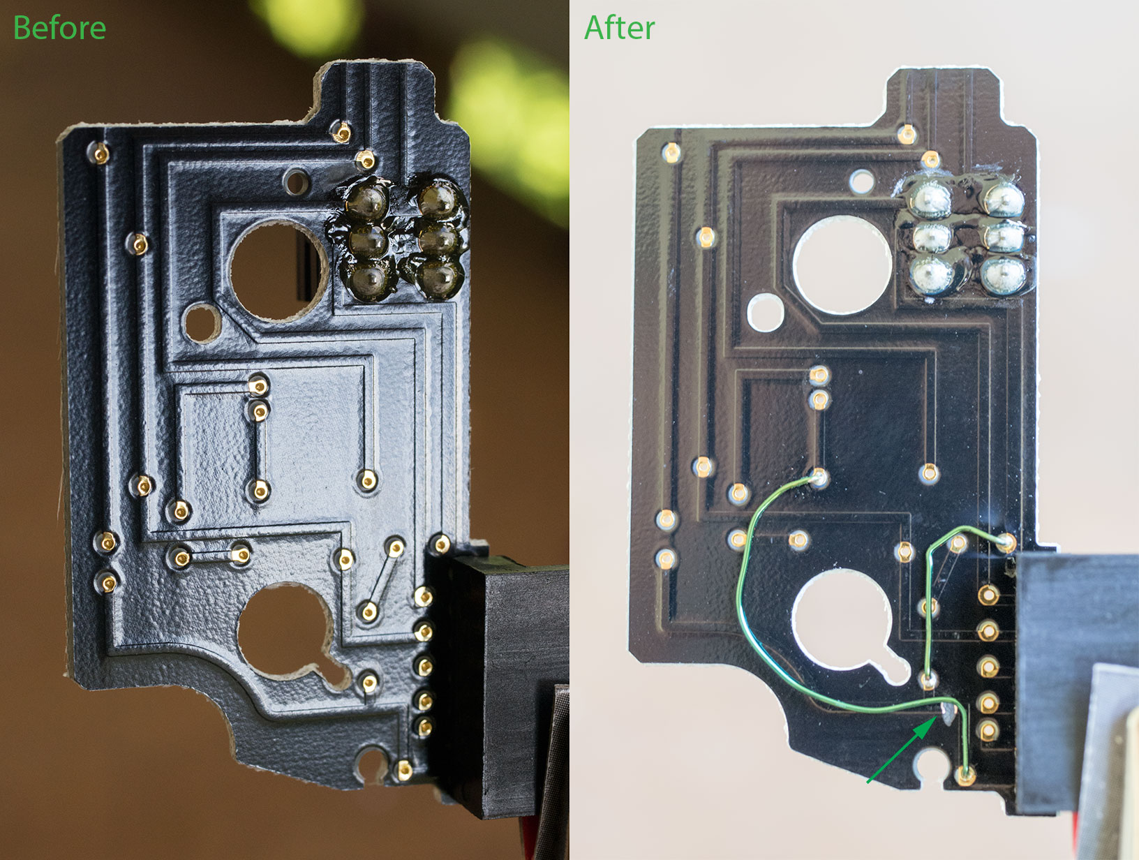
- A side effect of adding the wires is that the board will not fit back into its housing again. Thus, you need to use the milling tool to grind away some of the back panel plastic to allow the modified board to fit.
- Reassemble the switch module and test that the circuits function as my main diagram indicates they should.
Rewire the steering wheel sub-wire
The next stage is to rewire the sub-wire that goes in the steering wheel to separate the new cancel circuit on its own pin to the cable reel. If you choose to buy one M/T version and one A/T version of the sub-wire, I suggest using the M/T version in the steering wheel and cannibalizing the A/T version to get the connector for the dash side of the cable reel. You will need one extra pin from the A/T version to add to the M/T version for the cancel circuit. There are plenty of extras in the A/T version, so it will not be an issue. Obviously, if you are interested in adding other steering wheel mounted controls you will need more pins, and you might need a third sub-wire to steal pins from.
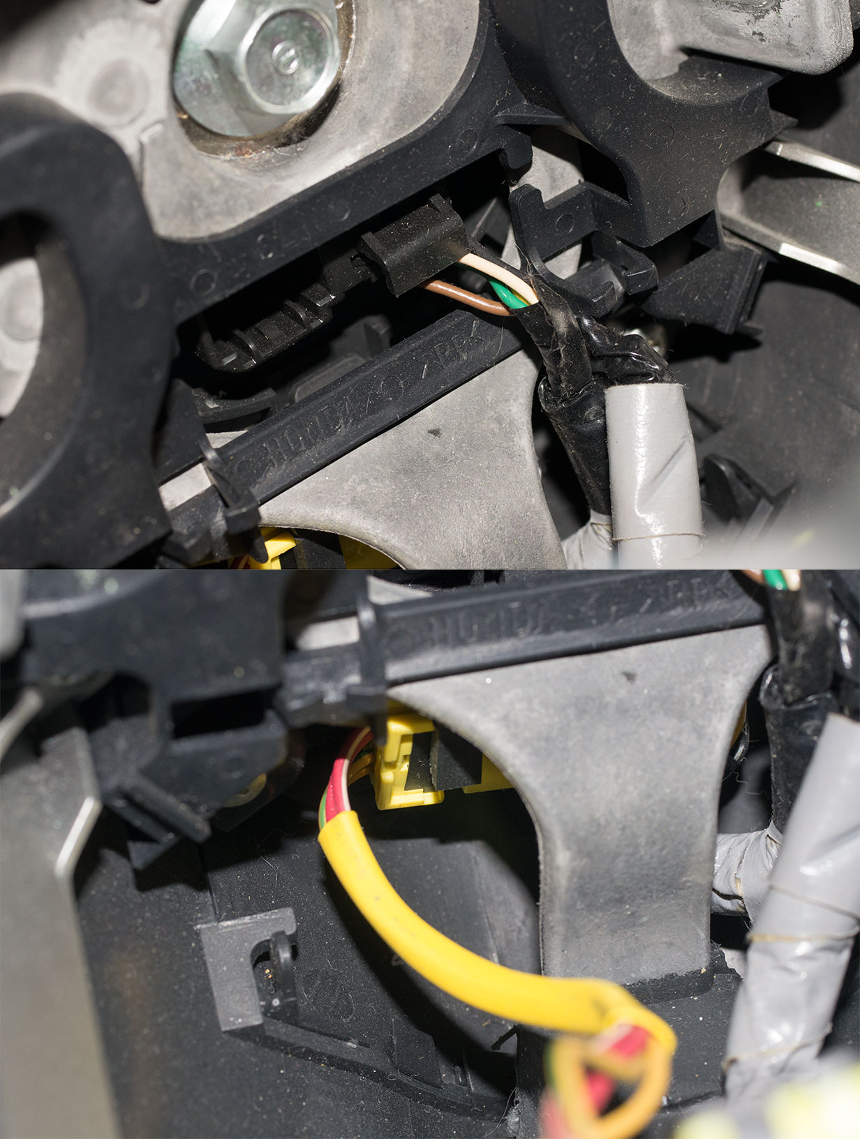
- Remove some of the tape from the sub-wire to expose the wiring:
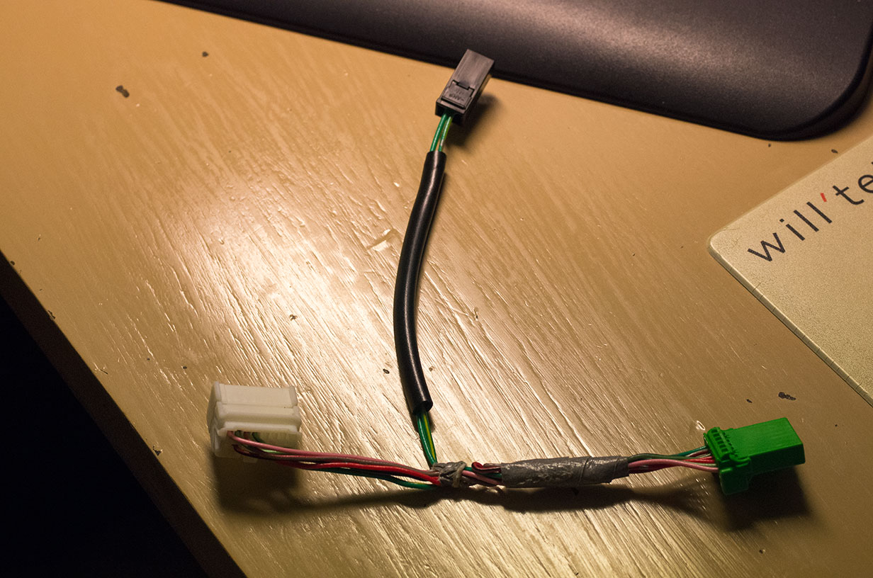
- There are two green/yellow wires going to the horn connector (middle below). One goes to the cable reel connector (right below) and the other goes to the switch module connector (left below). Cut the green/yellow wire that goes to the switch module at the point that it connects to the horn connector. This will give you your cancel wire to connect separately to the cable reel connector.
- Make a solder joint to connect the pin that you took from the cannibalized sub-wire for the dash side to the green/yellow that you cut before. Then insert the pin into an available pin location in the cable reel connector. It can go in any available pin position since you will be adding/re-purposing a pin on the dash side connector to match it.
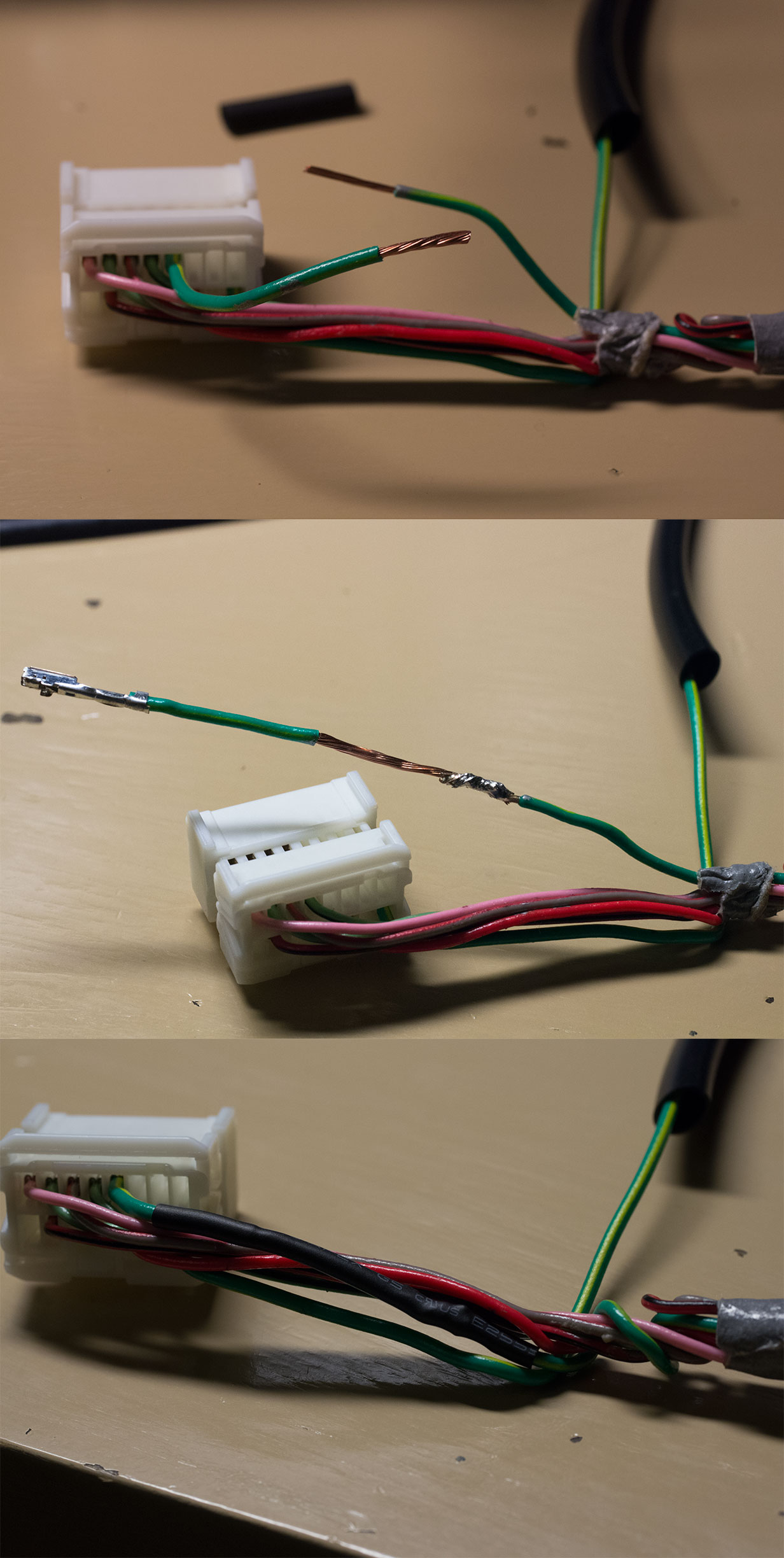
- Re-tape the wires to finish the steering wheel sub-wire.
Making the cruise wiring harnesses
The Rostra kit comes with three wiring harnesses:
- The main harness that connects to many of the cruise inputs.
- The control harness that connects to the buttons.
- The accelerator harness that connects to the accelerator.
Because of the lights circuits and the cancel circuit, the main and control harnesses end-up becoming one really. See the following overview of the finished harnesses:
On top is the main harness. In the middle is the control harness. On the bottom is the accelerator harness. The mid-way break-out on the main harness is for the back side connections for the fuse panel. The mid-way break-out on the control harness is for the lights- connection to the gauge module. The total length of the control harness is its length from the kit plus a few inches from the cannibalized sub-wire for the back of the cable reel. One thing to note is that you will need extra wires to use for the lights+ and lights- circuits. I used extra wires from the kit itself. There are a number of unused wires on the main harness that you will want to cut off that can be used. In addition, the VSS wire is about 3 times longer than the others on the main harness. I cut it short to match the length of the others and used the extra for the lights+ circuit. The way I laid it out, the lights+ wire ends-up being one of the longer ones since it has to come back from the control harness, then into the main harness to get to the back of the fuse panel. Below is a before and after picture of the control and main harness connectors to the cruise module (and the accelerator after):
Note the wires that I cut off. These are not used. However, if you are trying on the M/T, you will want to have the white wire included in the main harness. I left a bit of length on it just in case I was wrong about which clutch circuit to use for the cancel! Also note the yellow wire for the cancel jumping over to the control harness and the lights+ purple wire going between the two as well.
On the other end of the control harness you will want to remove the connectors from the kit and splice in the cannibalized sub-wire connector for the back of the cable reel. Again you can choose to put the circuits on any pin you want as they go though the cable reel as long as they match on both sides, and you get the circuits from the main diagram working. However, it makes sense to use their default locations and just add the cancel circuit.
For reference this is the accelerator harness that you want to use:
The kit I received had two different accelerator harnesses in it. You want the one with the larger connectors.
These harness lengths allow for the cruise module to be located to the right of the fuse panel as shown with the harnesses routed over the hanger bar above:
This was the best place I could find for it.
Steering wheel work
The next stage of work is the first on the car itself. The steering wheel needs to be removed and the cable reel swapped. Also the cruise buttons and the modified sub-wire need to be installed into the steering wheel.
- First disconnect the battery. I can never remember which pole is supposed to be disconnected, so I disconnected both.
- The next thing I did was remove the steering column covers. Unfortunately, I don't have many pictures of this. In addition, it might be easier to remove these covers after removing the steering wheel itself. There are two covers, a top and a bottom. The top cover clips to the bottom one with 4 plastic clips. The bottom cover has 3 screws that hold it onto the column. I think the way you are supposed to remove it is to unclip the top cover first and then unscrew the bottom. The plastic clips that hold the covers together are hard to pop loose and seem prone to breaking. Below is a picture of the clips after I broke them:
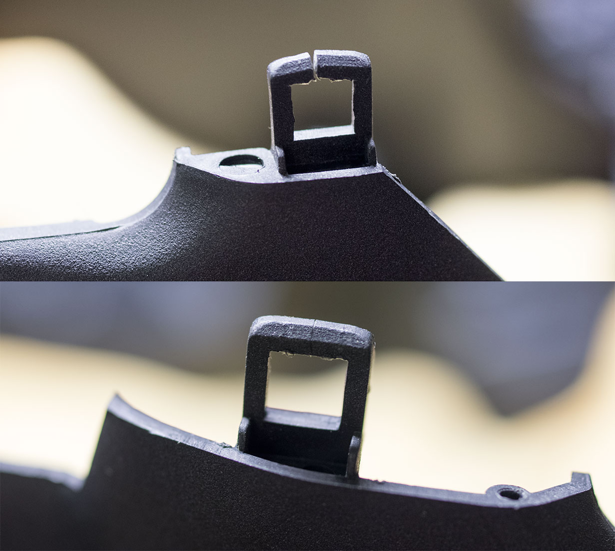
I glued the the clips back together with superglue. I think that maybe you are supposed to use a small blade tool such as a putty knife to push in under the clips pictured above to release them. The HSM doesn't provide much guidance on this one. - Remove the two airbag bolts on either side of the steering wheel with the Torx T30 bit:
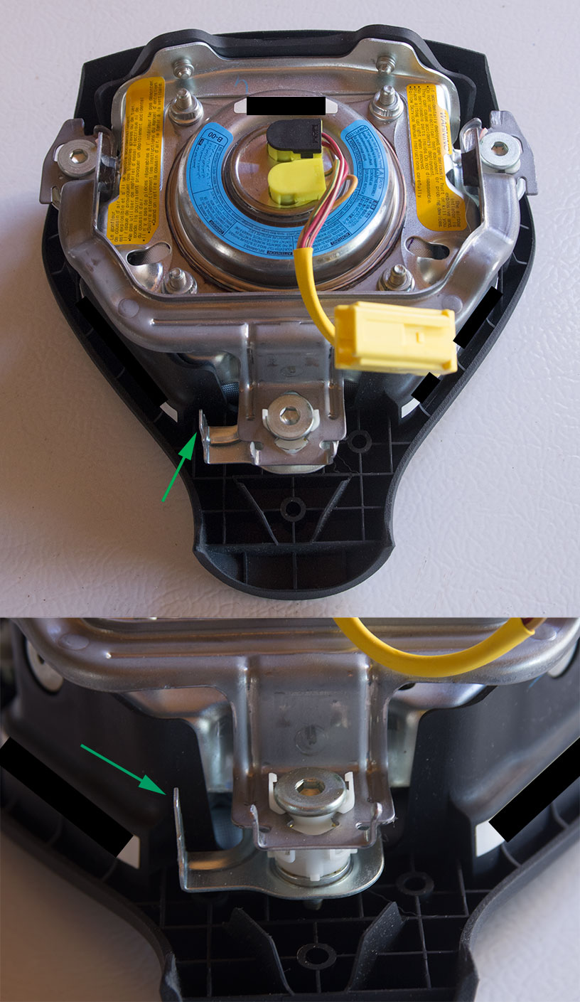
The back of the airbag:
The horn wire and the airbag connector:
- Disconnect the airbag and horn connectors. There is a panel on the bottom of the steering wheel that can be removed to make disconnecting the airbag connector easier. The horn wire has a connector that plugs directly into the airbag near the bottom.
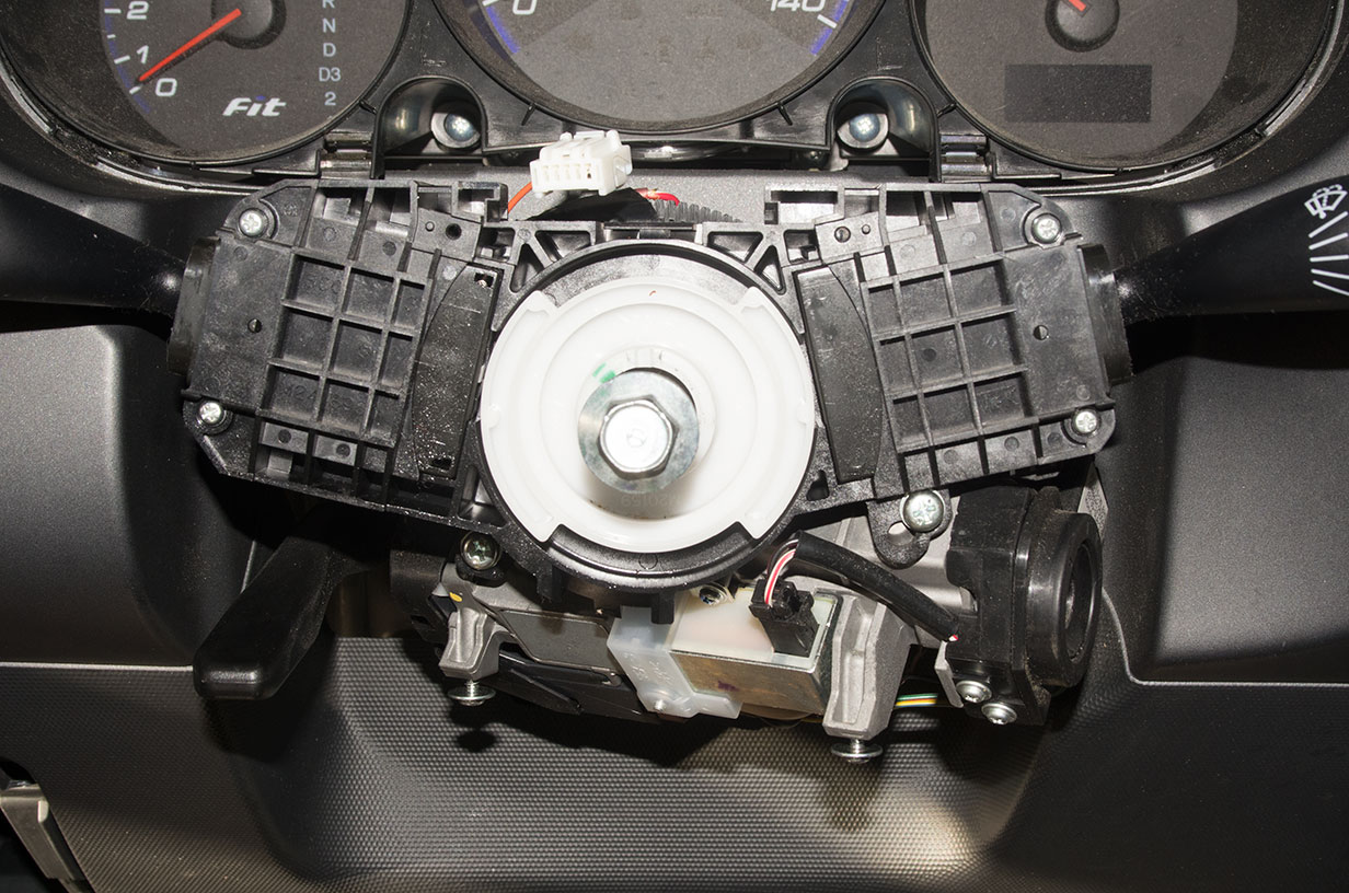
- Once the wiring is disconnected, the airbag is free, and the following is exposed:
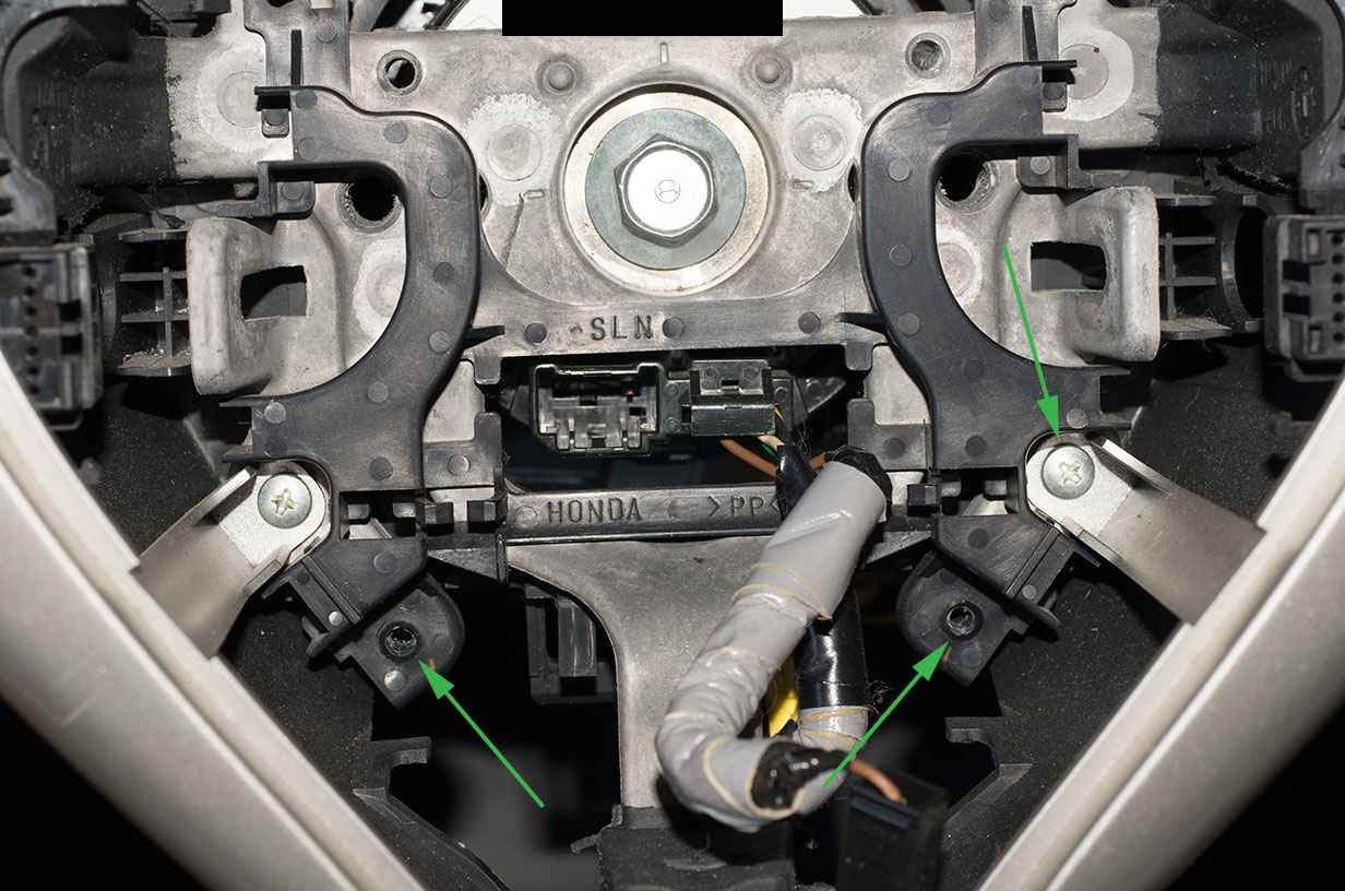
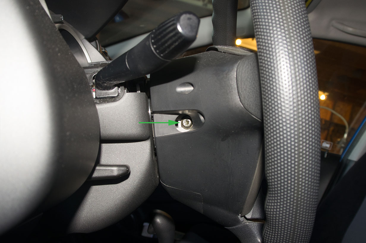
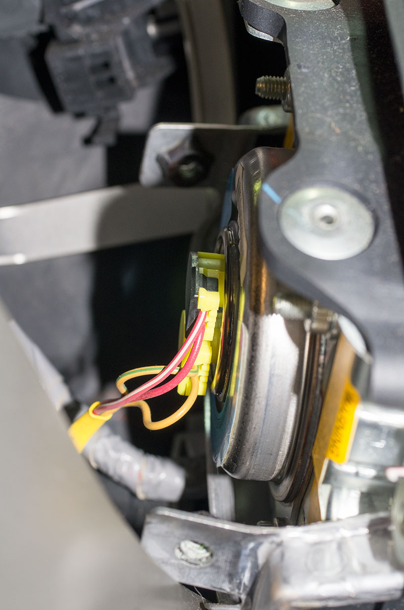
- Remove the main steering wheel bolt in the middle. I bought a steering wheel puller tool, but ended-up not needing it since the steering wheel was basically loose after removing the bolt. The other screws marked with arrows will also need to be removed to free the switch module trim panel and the wire guide.
- Remove the steering wheel to expose the cable reel:
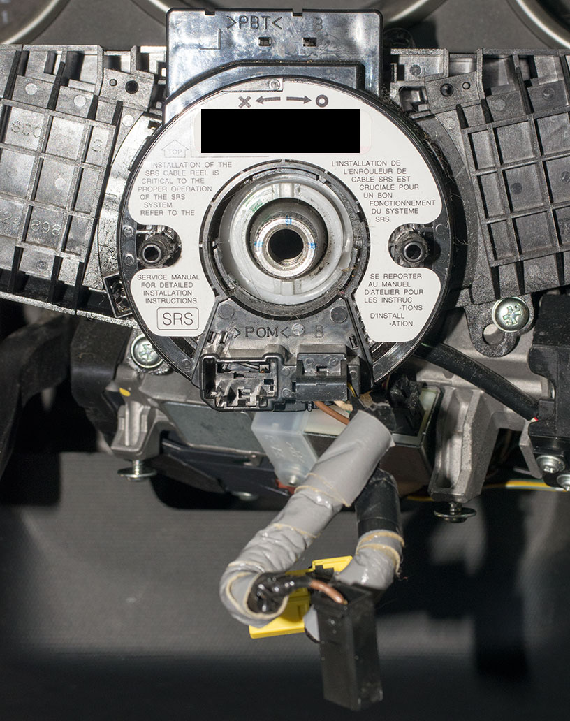
- If you choose to remove the steering column covers after the wheel, you will need to remove those now to remove the cable reel. Disconnect the horn wire connector on the back of the cable reel, and disconnect the airbag connector for the cable reel as well. If I remember correctly, the airbag connector is on the bottom of the steering column connected by a small length of wire to the cable reel.
- There are some clips that hold the cable reel onto the combination switch which come off easily. The cable reel can now be removed to expose the combination switch:
- At this point you can start putting things back together! Put the sport cable reel in where the old one was and connect its airbag connector on the bottom of the steering column where the old one was connected.
- Note that the horn wire that is disconnected from the cable reel has a connector that is similar to the connector for the sport cable reel (type A). Eventually when you put in the cruise control harness, you will want to remove the horn pin from this connector and put the pin into the new cable reel connector on the harness (pic later below). For the time being, you can use an extra cable reel connector to replace the connector on the horn wire, if you bought more than two of the steering wheel sub-wires. Otherwise you can leave it unconnected for now, but you will not have a working horn until you install the control harness later.
- Next remove the screws from the steering wheel to remove the blank trim panel that is in the place where the cruise buttons go.
- Remove the wire guide from the steering wheel and put your modified sub-wire into it as shown:
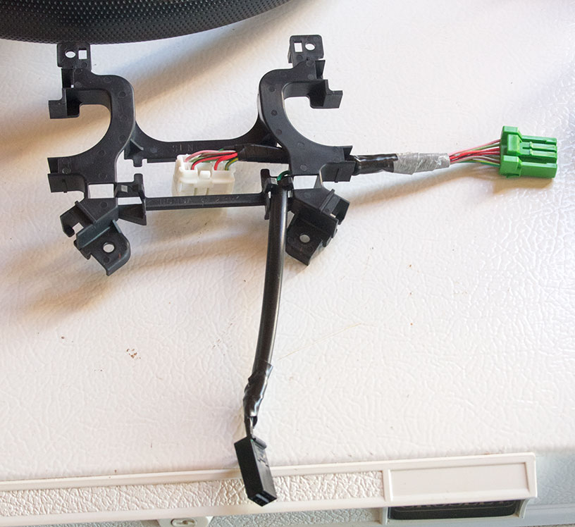
- Install the guide and sub-wire back into the steering wheel.
- Install your modified cruise buttons in place of the blank trim panel and connect the sub-wire connector to the button module.
- Now put everything back together the way it came apart, except of the steering column covers. You will want to leave them off for installing the control harness. The following picture notes the location of the horn connector on the airbag for reference:
- Note for the reassembly that the steering wheel bolt should be tightened to 29 lb�ft. Don't forget to use the new airbag bolts when reinstalling the airbag. The airbag bolts should be tightened to 7.2 lb�ft. (Numbers from the HSM.)
Gauge module and wiring work
The next stage is to remove the gauge module and do much of the general wiring work.
- Disconnect the battery if not already done.
- Remove the top silver trim around the gauges by gently pulling straight out on it. It is held on by a number of clips. This will expose the next layers:
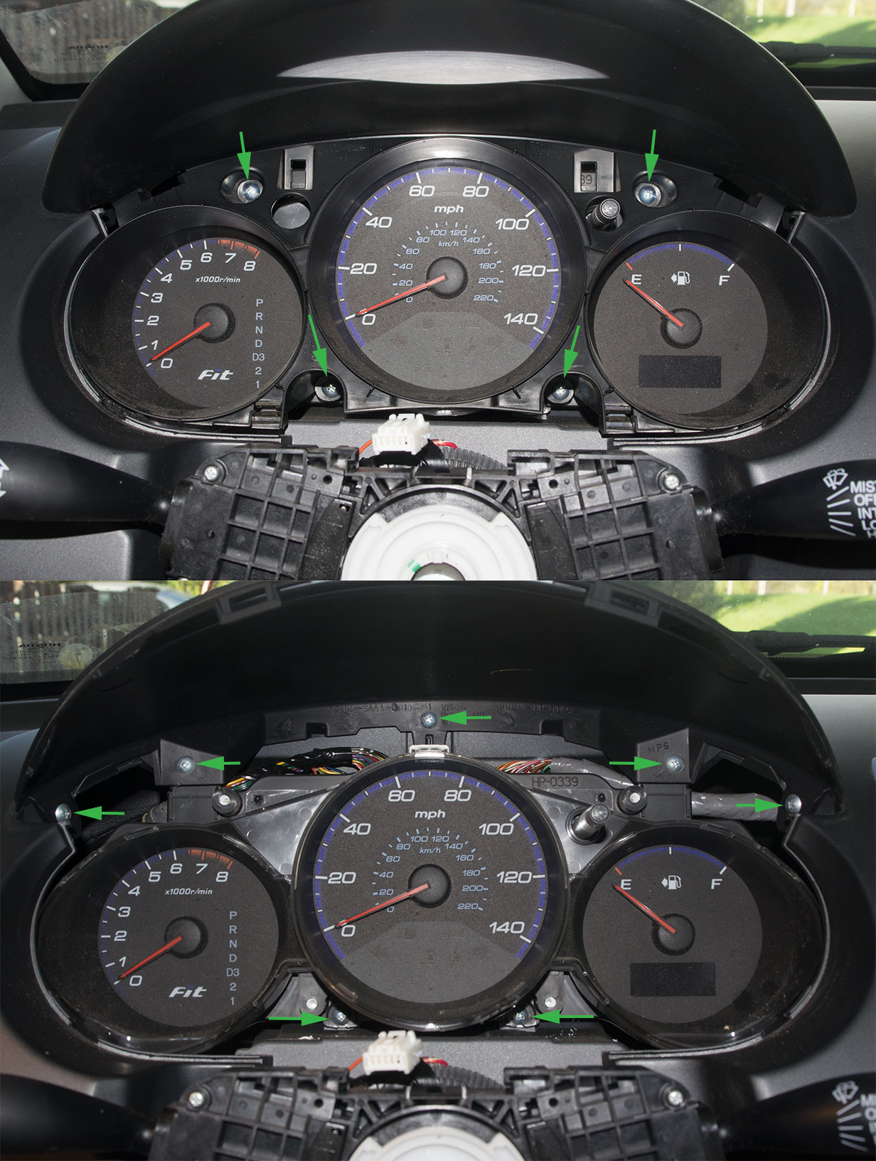
- Remove the screws indicated in the top picture and gently pull that plastic part out. The same part goes up under the visor and has clips along the top edge. These all come out fairly easily.
- Remove the top 5 screws in the second picture to remove the visor. Then remove the bottom two screws to free the gauge module.
- Unplug the three connectors on top of the gauge module and lift the module out:
- You are now ready to put the cruise module in place and route the new harnesses. You can follow the last picture in the "Making the main cruise wiring harnesses" section. I generally tried to follow existing harnesses and wire-tie the new ones to them as much as possible. All of the harnesses coming from the cruise module go over the hanger bar then then continue in different directions. The main harness goes down behind the fuse panel and loops back up in front of it with the existing harnesses. The control harness loops down and then up the harness that goes up the steering column, staying on the bottom for the most part. The accelerator harness is really longer than it needs to be, so I had it go up into the back of the dash space and then over to the accelerator side. I also guided it through part of the structure that supports the brake pedal to hold the harness in place.
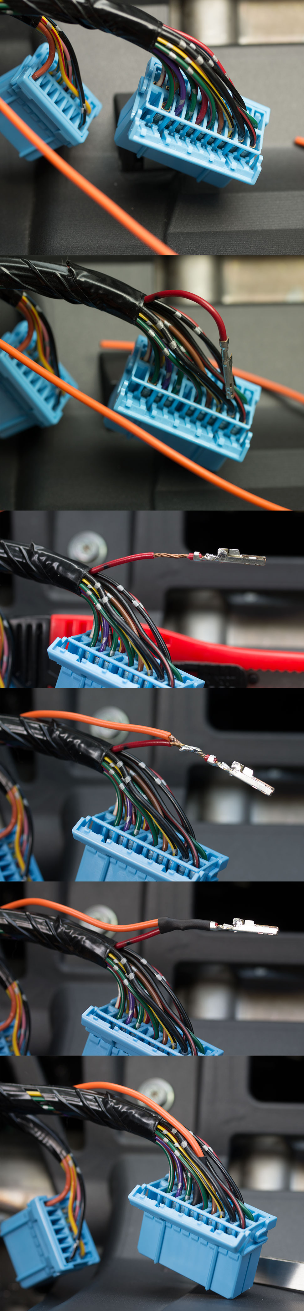
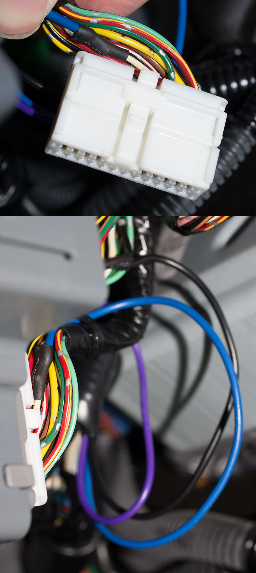
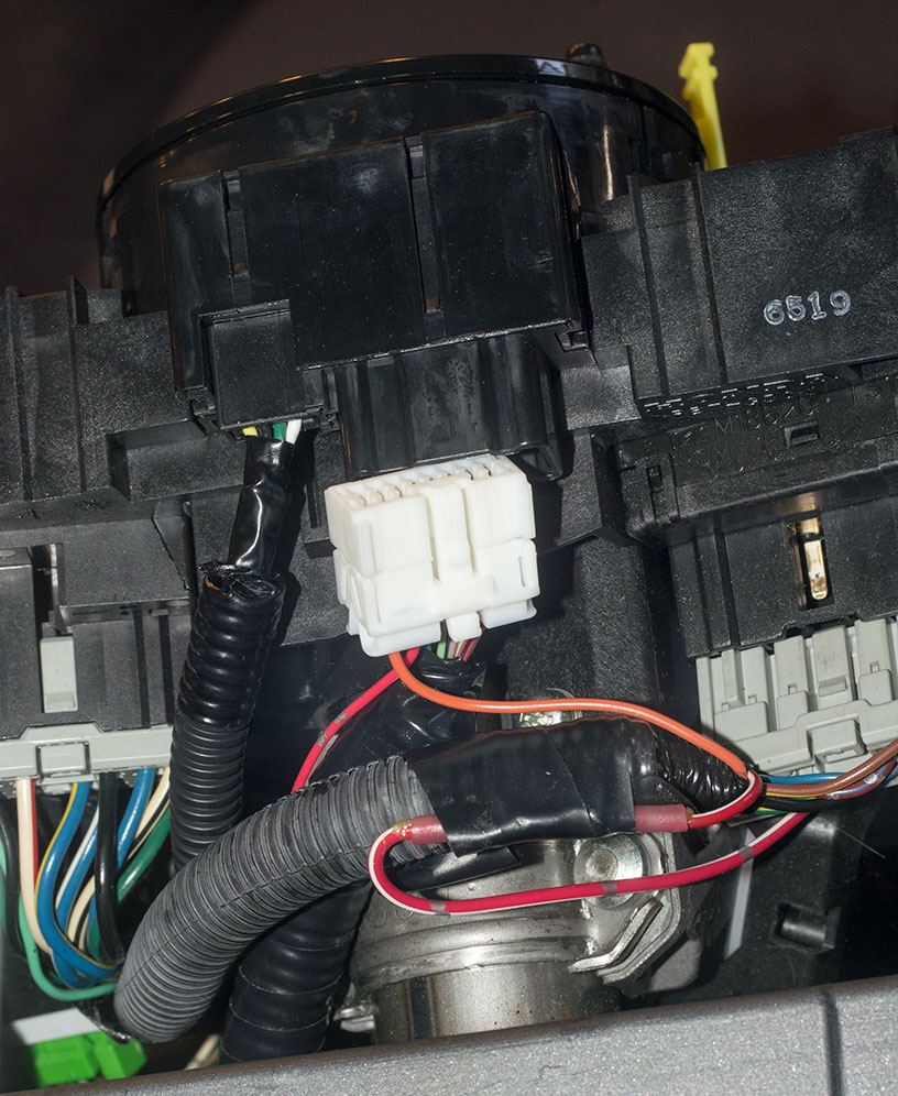
- Next you can plug your new control harness into the back on the cable reel. As noted above, the horn connector pin needs to be removed from its connector (type A) and inserted into the connector for the cable reel. See the orange wire in the following picture:
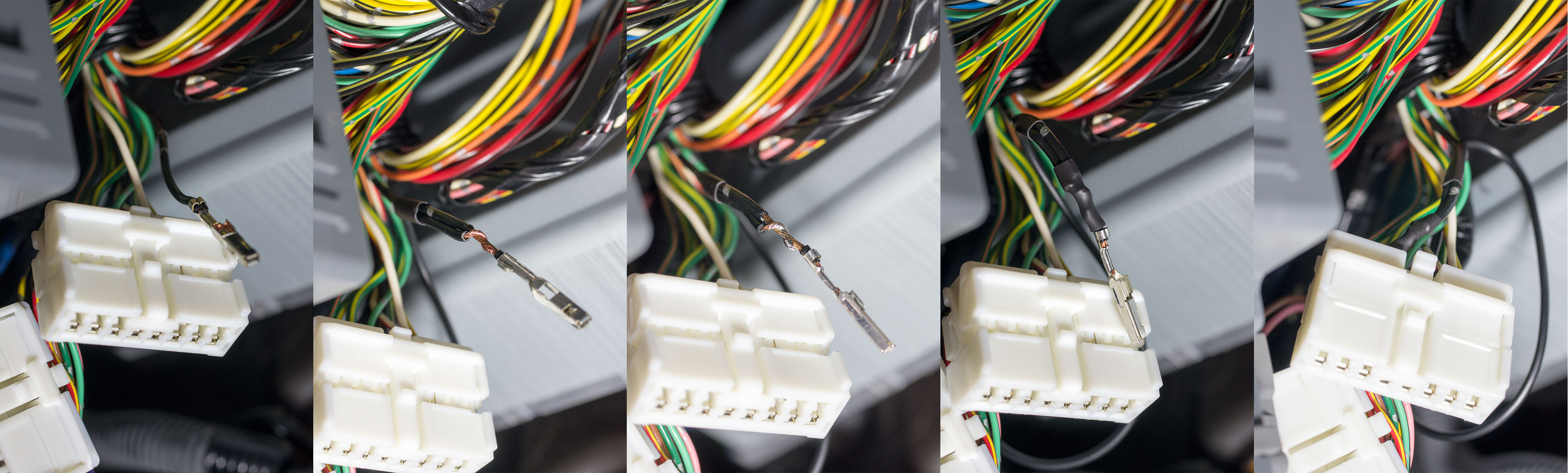
- Next make the connection for the lights- circuit on the gauge module connector. Refer to the picture above in the description of the type B connectors. The example in that picture is the gauge module connection. The general procedure is to remove the pin for the circuit that you need to join to, and strip off a small section of insulation near the pin. Then solder the new wire to it and put heat-shrink tubing over the joint. Finally put the pin back into the connector. This will be the same for all wire solder joints.
- Put everything back together the way it came apart including the steering column covers.
Fuse panel wiring connections
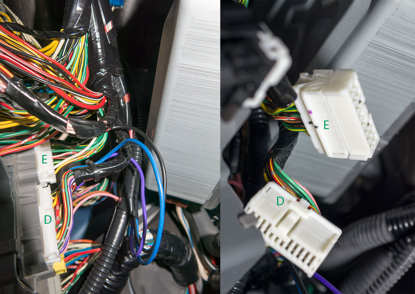
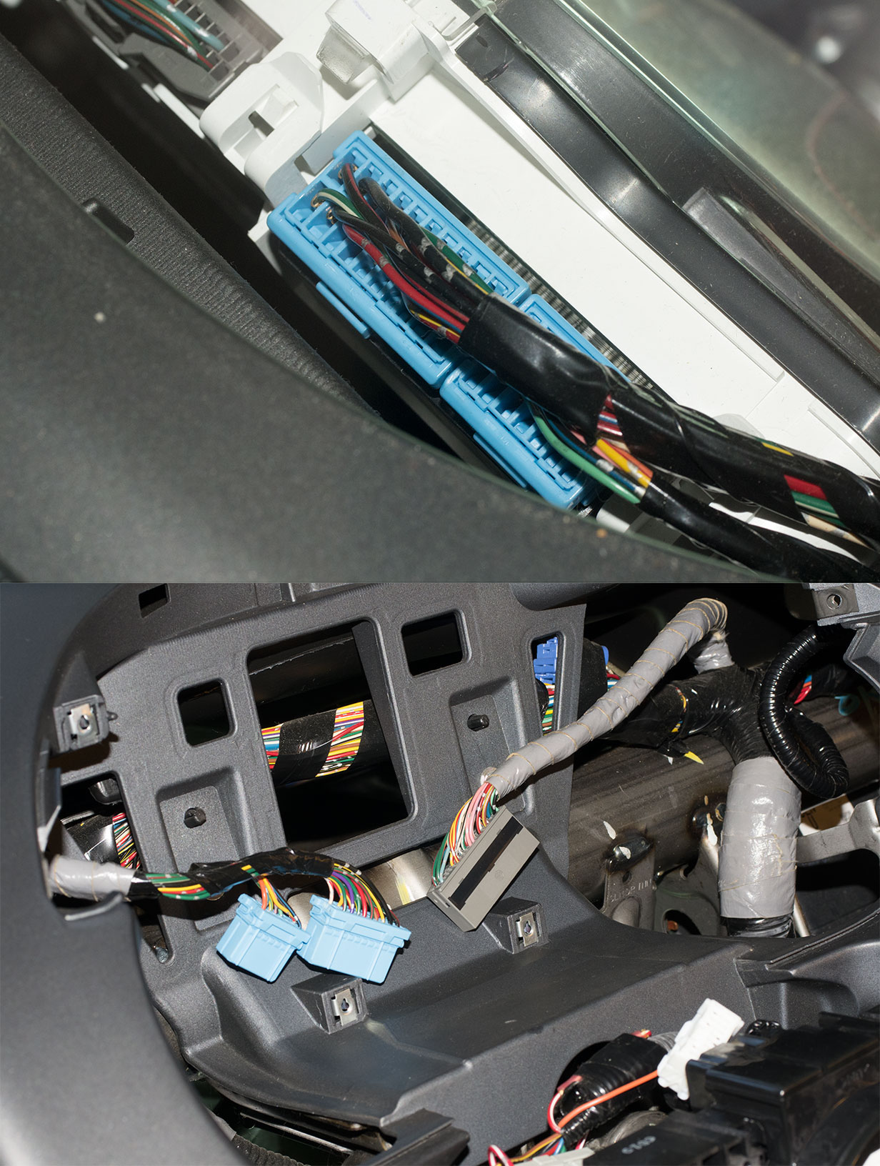
There are 6 connections that need to be made around the fuse panel, 3 on the front and 3 on the back. The following picture gives the locations of the front side connectors we are interested in. This is a post modification picture and the arrows indicate the routing of the main harness.
The next picture shows the back connectors we are interested in. Also note the break-out from the main harness for the back connection wires.
Another picture of the back connectors:
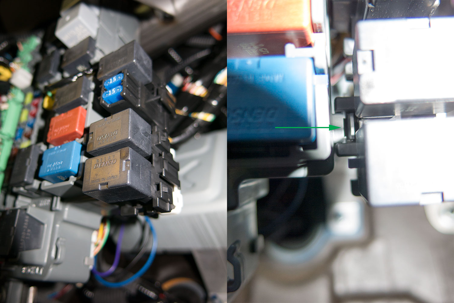
Something that will really help with working on the back connectors is detaching the two fuse blocks on the end of the fuse panel. There is a tab (shown below) that releases them and they can be pulled forward and detach from the fuse panel. They can then be pushed to the side to allow better access to the back of the fuse panel.
- Disconnect the battery if not already done.
- I tackled the back connectors first. Starting with the upper connector E (a type A connector):
- I then did the two connections on the lower connector D (also a type A connector):
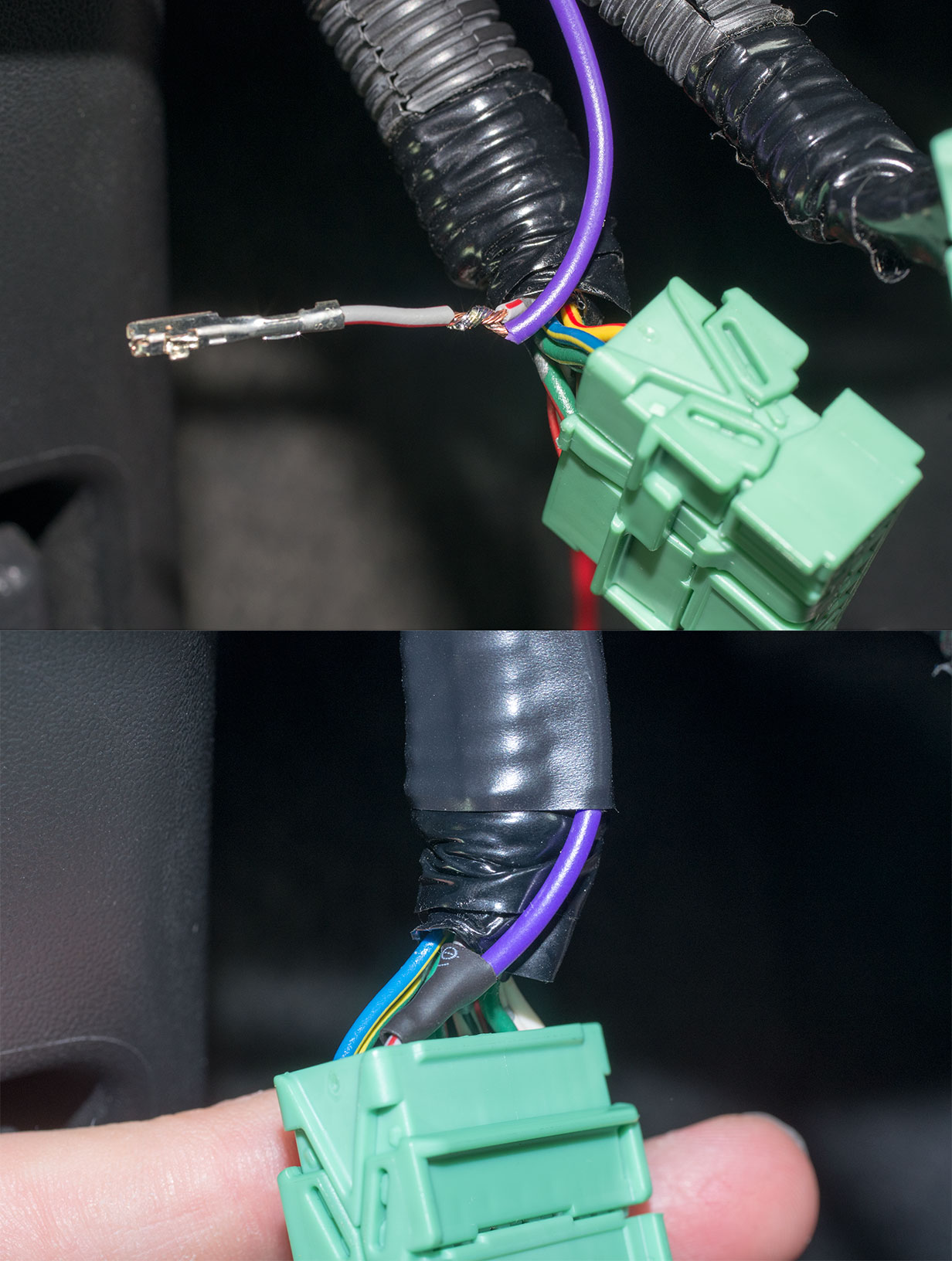
- Moving on to the front side connectors, I did C204 (a type B connector) next. Note that many if not all of the front side connectors on the fuse panel will need to be unplugged to get to C204 as well as the others we are interested in.
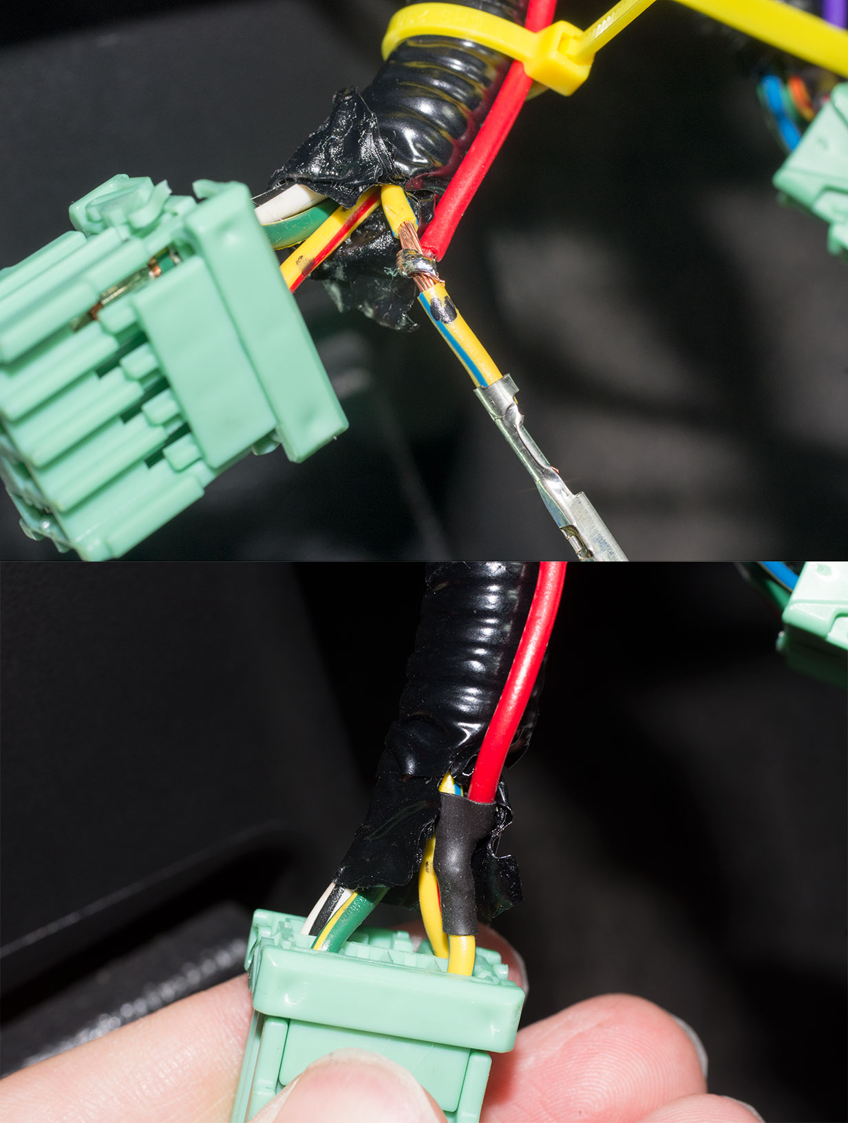
- Next comes connector B (a type A connector):
- And finally connector A (a type B connector):
- If you have made it here you are done with solder connections!
Connect the accelerator interface cable
- Disconnect the battery if not already done.
- Disconnect the accelerator connector and plug the cruise accelerator harness into the accelerator pedal. Plug the dash harness connector into the other connector on the accelerator harness.
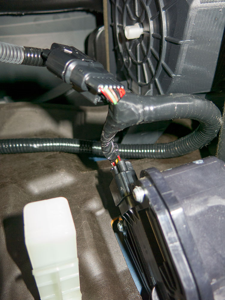
- It's done!!!
Thread Starter
|
Member
Joined: Dec 2010
Posts: 48
From: Michigan, USA
A few updates on this:
- The cruise seems to work pretty well. Holds speed well on most hills I have used it on. A few times it has gone down a gear on a hill, but fewer times than I expected.
- One thing that could be better is the speed step up and down while in cruise. It seems to respond too slowly to be useful in many cases. Also, it sometimes doesn't seem to give the expected result, and will go up or down momentarily, then return to the speed it was before. I think this is maybe tied to the slow response. In many cases it is easier to cancel the cruise, make the speed change, and set cruise at the new speed.
- While researching another mod, I found the following Honda diagram that I have tried, and it seems to be the correct way to remove the steering column covers. This diagram is for the Element, and the main difference is the Fit only has one set of clips on the sides of the column. Thus, the Fit has a total of 4 clips while the Element has 6.


Thread
Thread Starter
Forum
Replies
Last Post