
Dash disassembly, no changing colors


Thread Starter
|
Member
Joined: Jan 2011
Posts: 98
From: Lancaster, PA

Dash disassembly, no changing colors
So I really really wanted to be able to change the dash guage colors from blue to orange/red. So I bought a cheap gauge pod and radio to disassemble and see how they are put together.
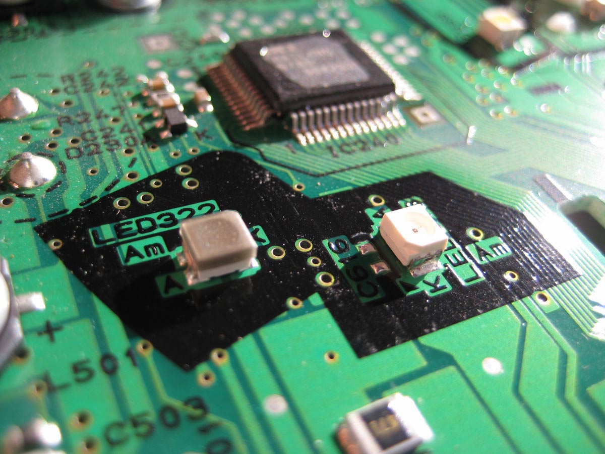
Well the bad news is that they are so highly engineered that it's rather difficult (I had previously said impossible, but if you are good with soldering tiny things then you could do it) to effectively change the colors of anything in the dash. All the LEDs are surface soldered and far too small for mere mortals to re-solder without fubar'ing the circuit board. There is another post here that shows the interior gauge film that can be replaced- problem is that is only half of the lighting situation. The same thing applies to the radio buttons and LCD. They are using directly colored LEDs to light things up for buttons and the speedo/tach/gas tick marks. The LCD is permanently dyed/tinted glass- so that's impossible to change too.
Check out my pics of disassembly here.
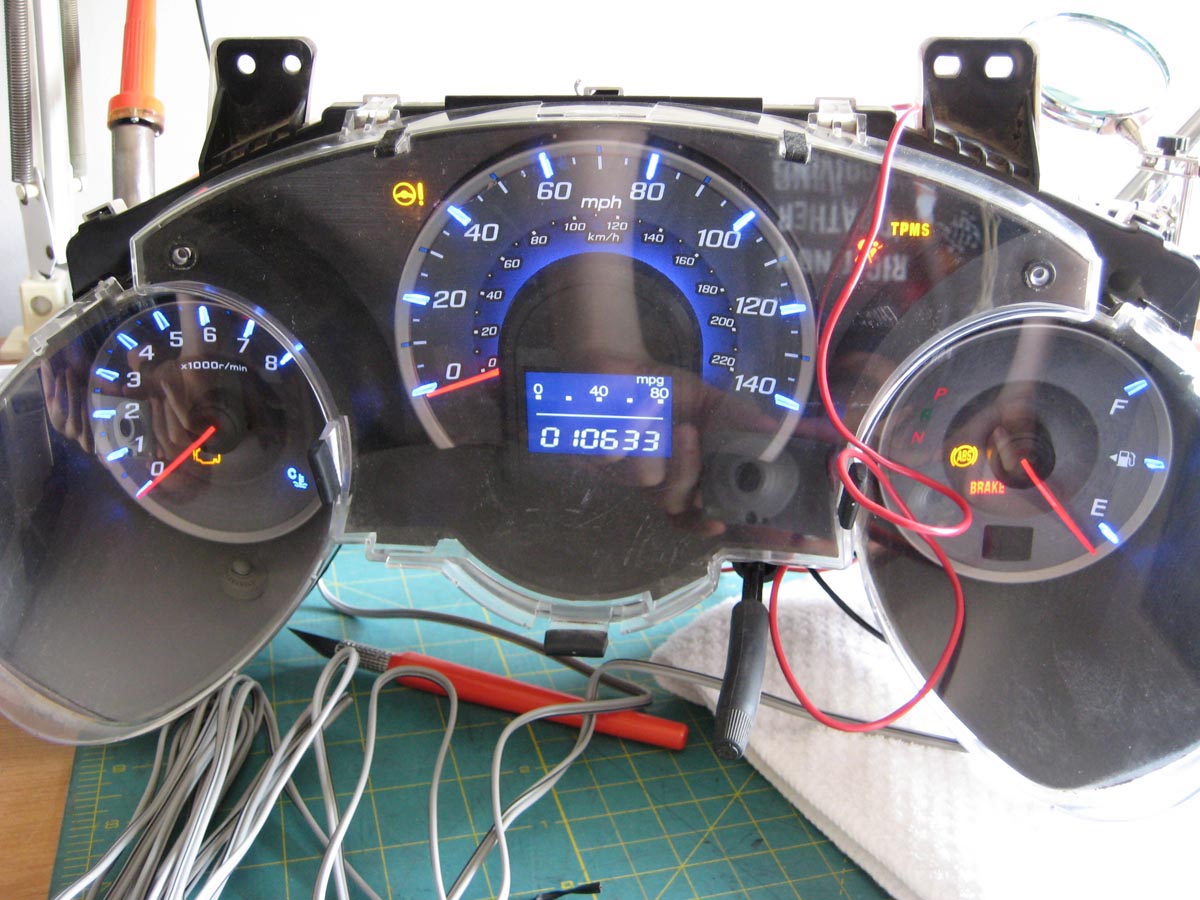
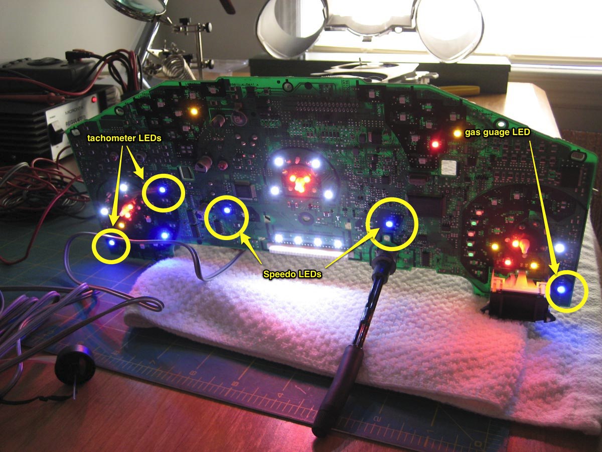
Test light up to make sure it works
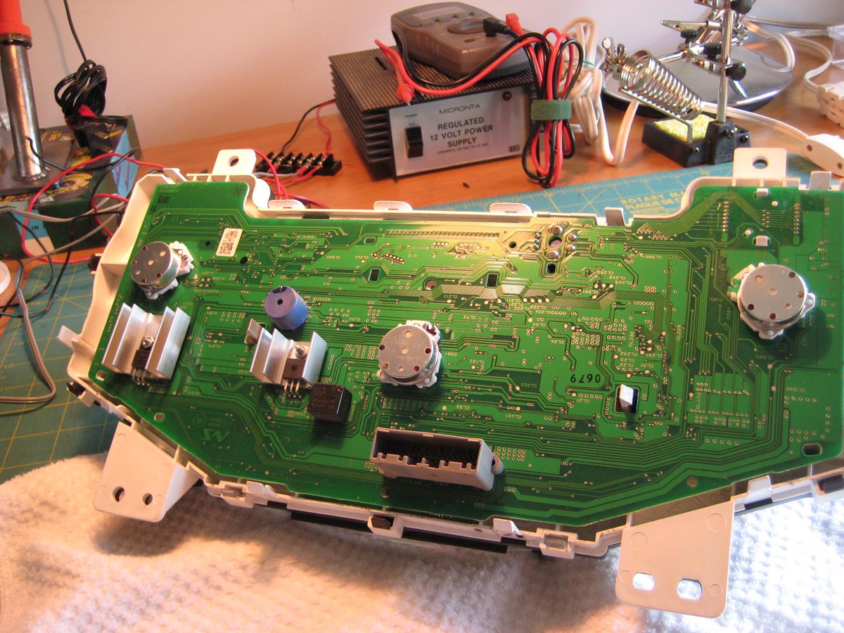
Back taken off. Circular parts and the needle... electrical servo's? Not sure how I describe them.
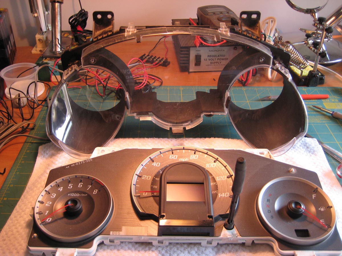
Front plastic off. You can't take the knob off.
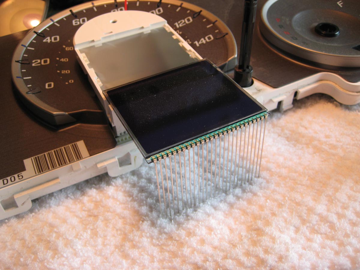
This is interesting: the LCD is not soldered on but only press fit into a plug where the long electrodes go through. After some direct upward pressure and gentle wiggle it can come out.
The needles pull directly out but require what seems like a lot of pressure. Don't turn them while you do it or you will mess up the calibration!
This is the bunch of reflector material behind the LCD panel.
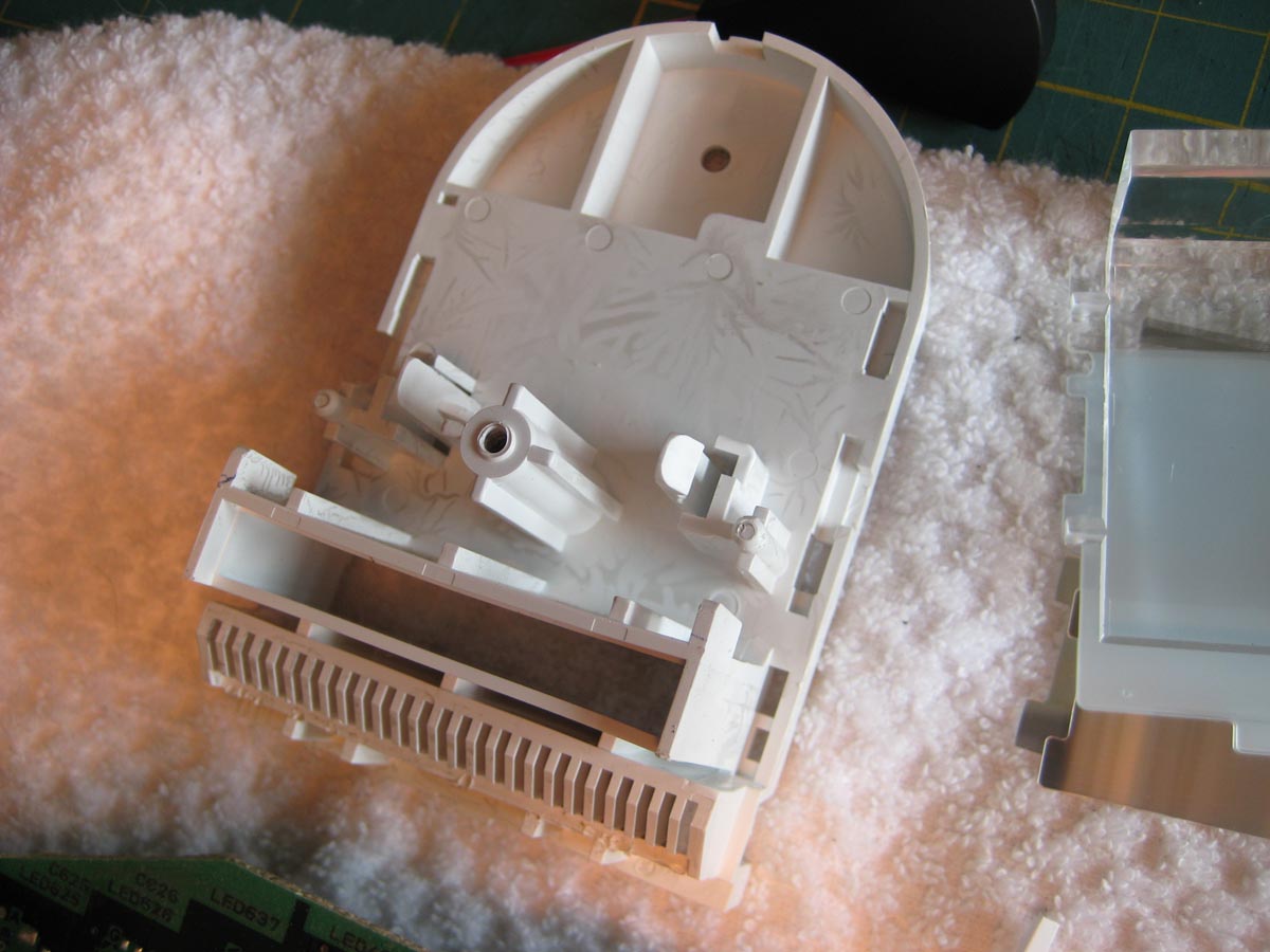
Here are 2 views of the LCD housing. The black surround can be pulled off, there are only 2 surface mount plastic tangs inside the black housing. To pull this white part off, there are 2 barbed tangs. You can sort of push them from the 2 slots in the middle you see here.
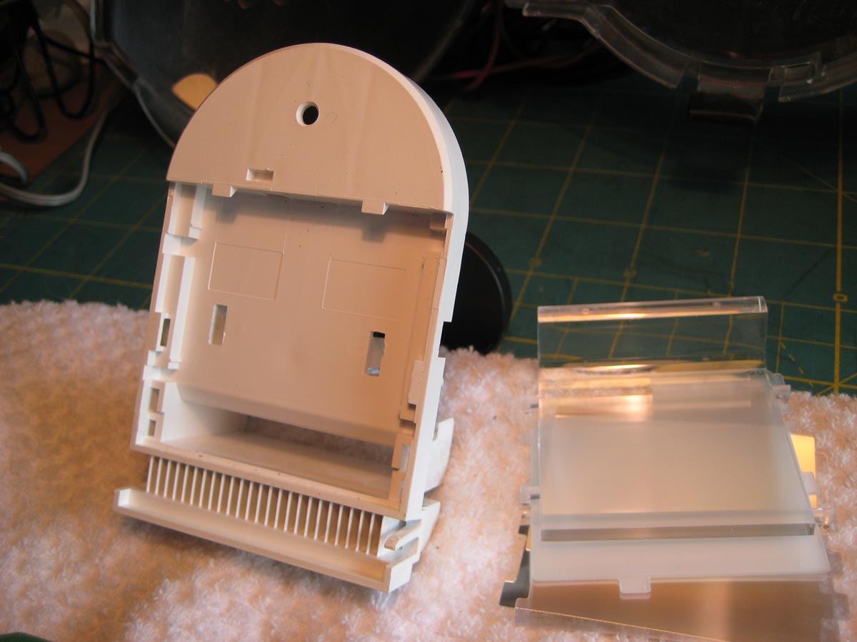
Here is the back of it.
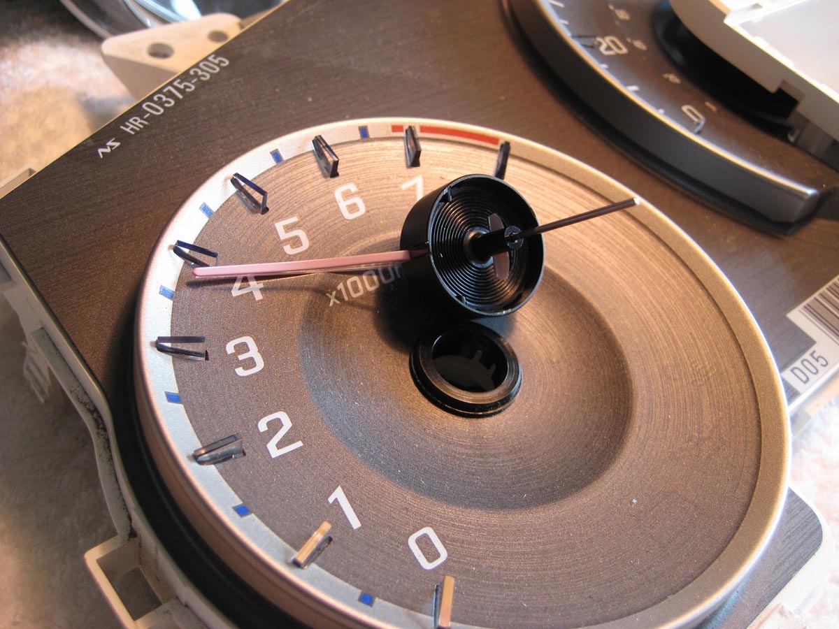
Here is the guage back with the grey printed part taken off. That has a little clip in the center of the speedo needle, and small black ferrules around the gas and tach needles that need to come off first. The plastic printed piece has a few colored items printed in it- PRNDL settings and the blue "glow" part in the middle of the speedo. So that's not possible to change the color, but is easy to paint black if you want to get rid of that.
In this picture you can also see the different windows for lights. In the middle of the speedo is a large clear plastic moon shaped piece. This is for the speedo marks that light up. Lightly attached to it is the blue secondary color reflector piece.
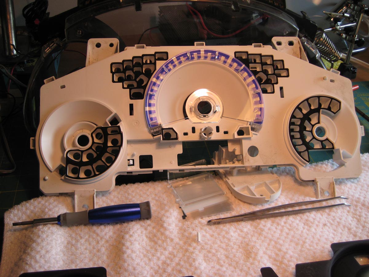
Here's the heart of the problem. The gauge LEDs are colored already, blue.
The board
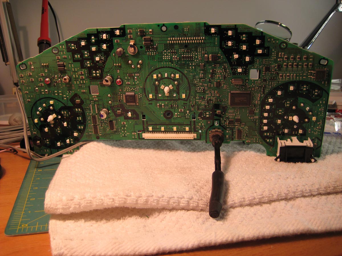
Surface mount LEDs
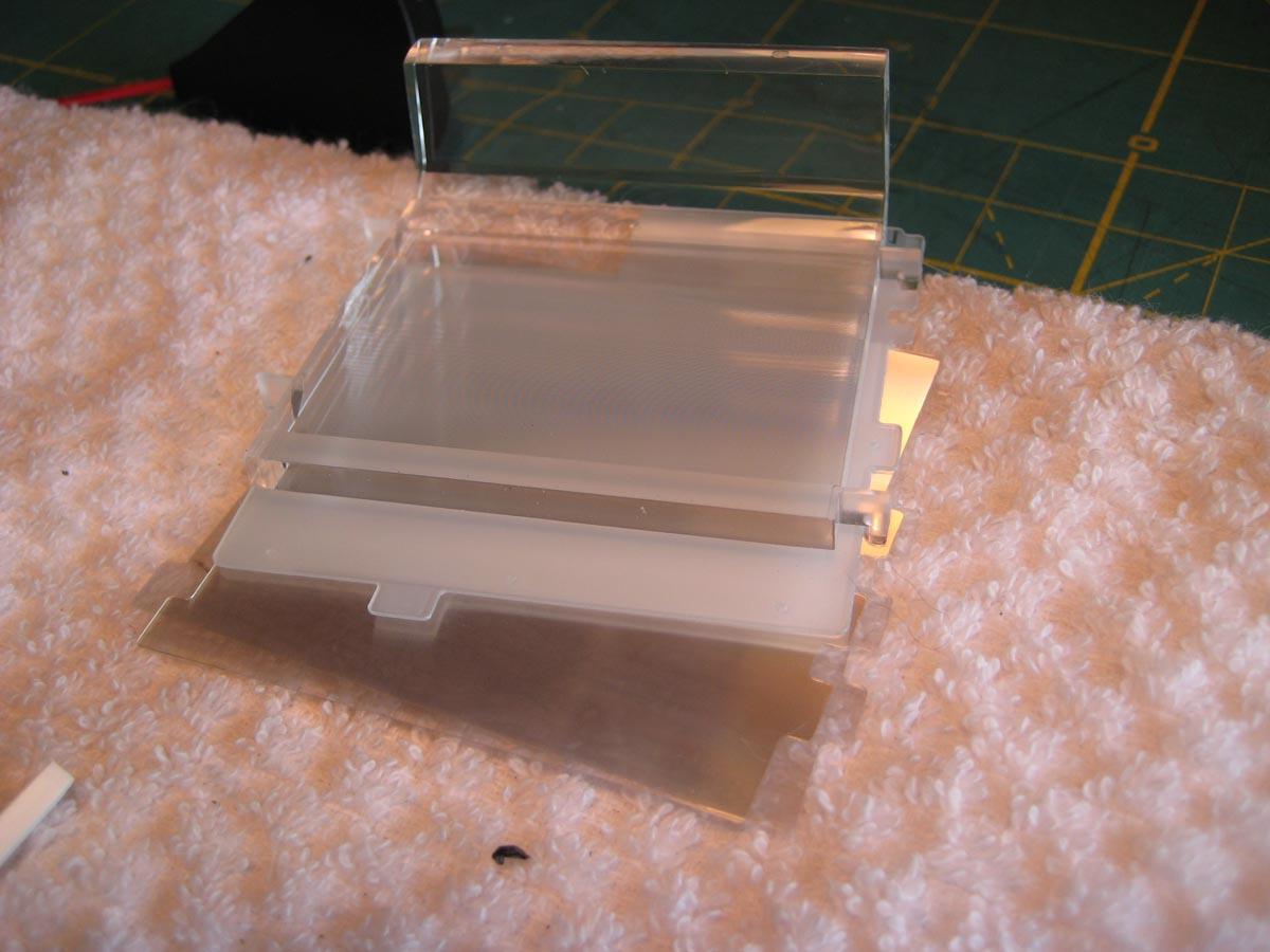
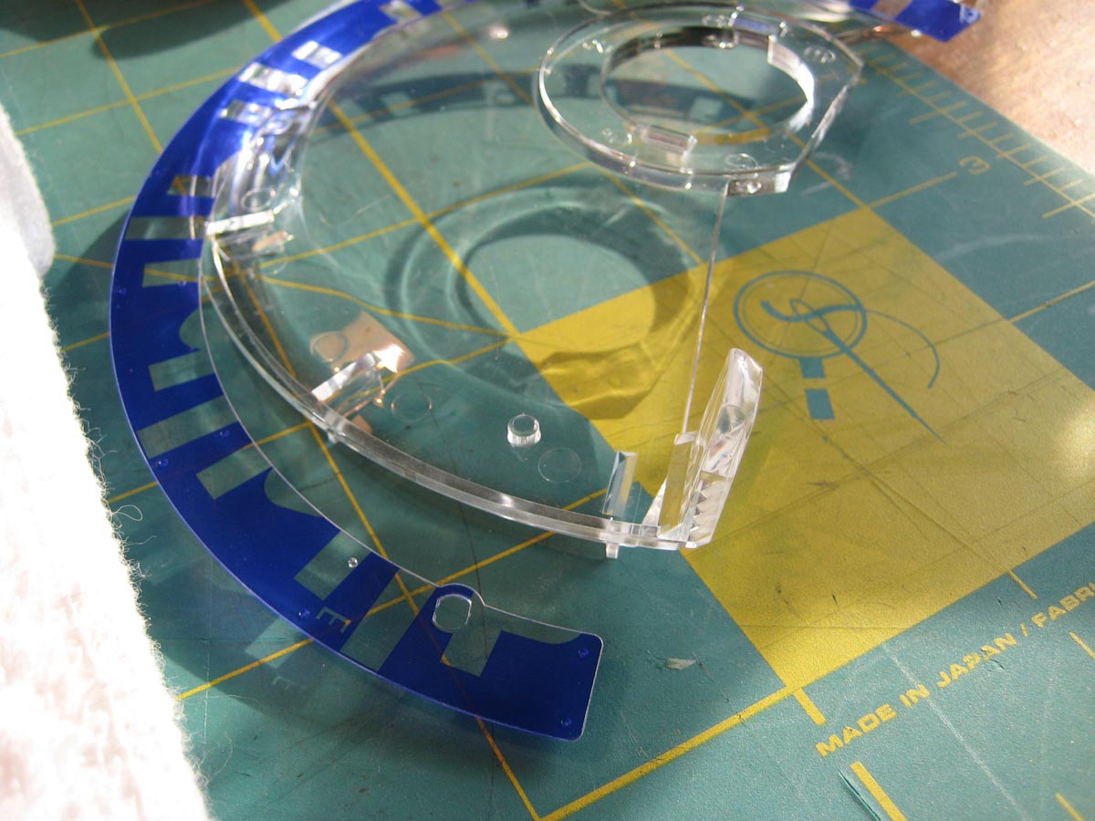
This is the light pipe for the LED speedo marks and the secondary reflector. The colored reflector IS NOT the primary source of color for the tick marks. The LED shines the light into the ends of the clear plastic and it has engineered little inner reflector angles to shoot the LED light out of the tick marks. Just like fiber optic strands work, but on a fatter scale- light reflects internally when it hits certain angles internally.
Check out my disassembly of a radio at this post:
https://www.fitfreak.net/forums/fit-...head-unit.html
Well the bad news is that they are so highly engineered that it's rather difficult (I had previously said impossible, but if you are good with soldering tiny things then you could do it) to effectively change the colors of anything in the dash. All the LEDs are surface soldered and far too small for mere mortals to re-solder without fubar'ing the circuit board. There is another post here that shows the interior gauge film that can be replaced- problem is that is only half of the lighting situation. The same thing applies to the radio buttons and LCD. They are using directly colored LEDs to light things up for buttons and the speedo/tach/gas tick marks. The LCD is permanently dyed/tinted glass- so that's impossible to change too.
Check out my pics of disassembly here.
Test light up to make sure it works
Back taken off. Circular parts and the needle... electrical servo's? Not sure how I describe them.
Front plastic off. You can't take the knob off.
This is interesting: the LCD is not soldered on but only press fit into a plug where the long electrodes go through. After some direct upward pressure and gentle wiggle it can come out.
The needles pull directly out but require what seems like a lot of pressure. Don't turn them while you do it or you will mess up the calibration!
This is the bunch of reflector material behind the LCD panel.
Here are 2 views of the LCD housing. The black surround can be pulled off, there are only 2 surface mount plastic tangs inside the black housing. To pull this white part off, there are 2 barbed tangs. You can sort of push them from the 2 slots in the middle you see here.
Here is the back of it.
Here is the guage back with the grey printed part taken off. That has a little clip in the center of the speedo needle, and small black ferrules around the gas and tach needles that need to come off first. The plastic printed piece has a few colored items printed in it- PRNDL settings and the blue "glow" part in the middle of the speedo. So that's not possible to change the color, but is easy to paint black if you want to get rid of that.
In this picture you can also see the different windows for lights. In the middle of the speedo is a large clear plastic moon shaped piece. This is for the speedo marks that light up. Lightly attached to it is the blue secondary color reflector piece.
Here's the heart of the problem. The gauge LEDs are colored already, blue.
The board
Surface mount LEDs
This is the light pipe for the LED speedo marks and the secondary reflector. The colored reflector IS NOT the primary source of color for the tick marks. The LED shines the light into the ends of the clear plastic and it has engineered little inner reflector angles to shoot the LED light out of the tick marks. Just like fiber optic strands work, but on a fatter scale- light reflects internally when it hits certain angles internally.
Check out my disassembly of a radio at this post:
https://www.fitfreak.net/forums/fit-...head-unit.html
Last edited by SuperMacGuy; Jun 14, 2013 at 01:32 PM.

Member
Joined: Aug 2012
Posts: 419
From: NYC
I dont see what's so impossible about replacing these LED's. all you need is a soldering iron, FRESH razor blade if your going the lazy cheapo DIY way (there is a soldering tip specially made for taking off IC's and the like which is much more professional and less messy), and finding out the sizes of these LED's which shouldn't be too hard seeing as most aftermarket LED replacement "bulbs" are of about the same type and size.
Thread Starter
|
Member
Joined: Jan 2011
Posts: 98
From: Lancaster, PA
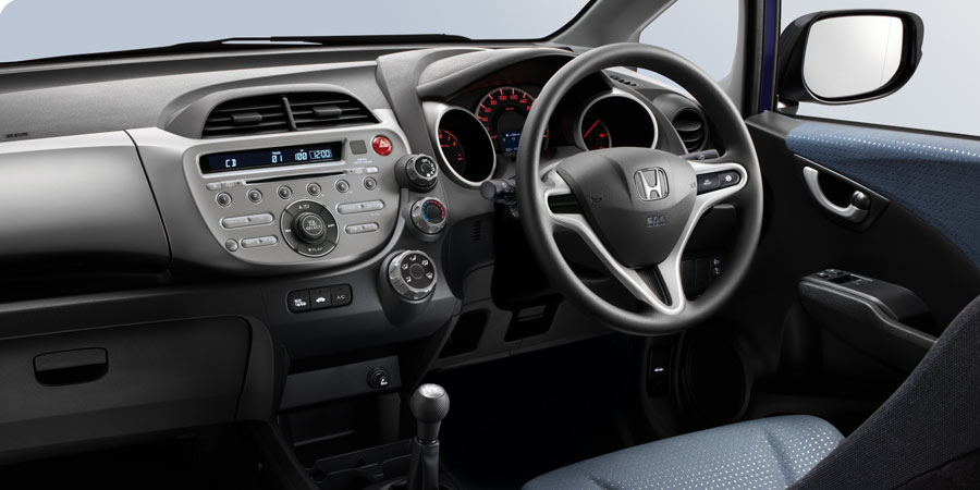
Well I have done some soldering but these are way way way smaller than I have ever attempted or have proper tools for. So maybe not impossible, but just for me to do. The UK Jazz DOES have a red guage pod, maybe I can retro fit that? It also has a black and white radio LCD.
From UK site:
From UK site:
Member
Joined: Aug 2012
Posts: 419
From: NYC
these LED's are actually on the larger side as i've worked with smaller LED's for game console repairs and color swaps. all you really need is melt the solder on 1 side of the LED and slid a FRESH razor in between the contact and the mobo, then carefully melt the solder on the other side and it slides right off. clean it up a little with some solder flux and desolder braid then reattach the new LED 1 side at a time. only problem i've encountered with this method is if you're lazy and dont test the polarity of the LED before putting it on you'll most likely be frustrated and redoing it.
Thread Starter
|
Member
Joined: Jan 2011
Posts: 98
From: Lancaster, PA
Is there a special soldering iron to work on things that small? Any tips or tricks? And how would I go about finding out the size and power (plus adjustable output too) if I wanted to order some different LEDs?

New Member
Joined: Jun 2013
Posts: 4
From: USA
SuperMacGuy,
Can you post pics and instructions on how to dissasemble the dash to get at the gauge cluster? Like where to pry with your trim tool and hidden screws? I want to replace my scratched up clear plastic.
Thanks.
Can you post pics and instructions on how to dissasemble the dash to get at the gauge cluster? Like where to pry with your trim tool and hidden screws? I want to replace my scratched up clear plastic.
Thanks.
New Member
Joined: Jun 2013
Posts: 4
From: USA
Thanks anyway, I found the link I need on the forum.
Scratched gauge cluster - Page 4 - Unofficial Honda FIT Forums
Scratched gauge cluster - Page 4 - Unofficial Honda FIT Forums
Aoyue 950+ Dual Function Repair Station > Soldering Stations > Main Section > SRA Soldering Products
You can just "tweeze" on both solder joints and just drop the piece to the side once it's off. Or if you have a solder set already just get the tweezer iron for it.
I do some circuit board rework at work with much smaller components than those LEDs. Would I use that iron at work? No. But it's probably fine for the casual user who will only use it two or three times a year.

Member
Joined: Dec 2009
Posts: 726
From: USA
Well I have done some soldering but these are way way way smaller than I have ever attempted or have proper tools for. So maybe not impossible, but just for me to do. The UK Jazz DOES have a red guage pod, maybe I can retro fit that? It also has a black and white radio LCD.
From UK site:
From UK site:
I came to what I thought was an even better conclusion. Purchase the European style cluster (red based), then I'll have both. If I get tired of the red, I can switch back to the original blue cluster -- which, I like better than the red cluster anyway -- and reverse. You have the best of both worlds for whenever you choose or get tired of the same cluster all of the time.
Would like to know what you decided to do.

Only problem with the JDM cluster is you have to re-pin it in order for the AC buttons to light up, hazard button to light up and the steering wheel control switches to work.
I have a few ideas on how to modify the us cluster based off this thread and another from a while back.
I have a few ideas on how to modify the us cluster based off this thread and another from a while back.
Here is the other thread I mentioned:
https://www.fitfreak.net/forums/2nd-...r-cluster.html
As you can see it gets more complex once you do the actual work. It can be done though.
https://www.fitfreak.net/forums/2nd-...r-cluster.html
As you can see it gets more complex once you do the actual work. It can be done though.

Thread
Thread Starter
Forum
Replies
Last Post
Austinite
2nd Generation GE8 Specific DIY: Repair & Maintenance Sub-Forum
3
Nov 22, 2013 02:52 PM
cupax
Fit Interior & Exterior Illumination
8
Jun 4, 2011 04:00 AM
dirtybird222
2nd Generation (GE 08-13)
9
Feb 17, 2009 04:35 PM