
D.I.Y: Blower motor Resistor Repair


Thread Starter
|
New Member
Joined: Mar 2013
Posts: 5
From: Havre de Grace, MD

D.I.Y: Blower motor Resistor Repair
Hello All,
I thought I would make a DIY on how to repair the blower motor resistor on our generation Honda Fits (mine is a 2011). The symptoms of it being bad is the infamous HVAC fan speed control only working on 4 (high). I took the time to investigate the issue and it appears that poor soldering at one of the solder joints is the culprit more so than an excessive current draw from the fan (as stated in the TSB which addresses the issue). Well, it worked for me and no blower fan replacement was needed........
Repair Procedure:
http://www.underhoodservice.com/wp-c...0000057441.jpg
Fig. 1
1. Remove the passenger-side dashboard undercover (see Fig. 1):
a. Gently pull down the front edge to detach the clips.
b. Pull the cover toward you to release the pins.
http://www.underhoodservice.com/wp-c...0000057443.jpg
Fig. 2
2. Remove the blower resistor:
a. Disconnect the connector.
b. Remove the two screws and the blower resistor.
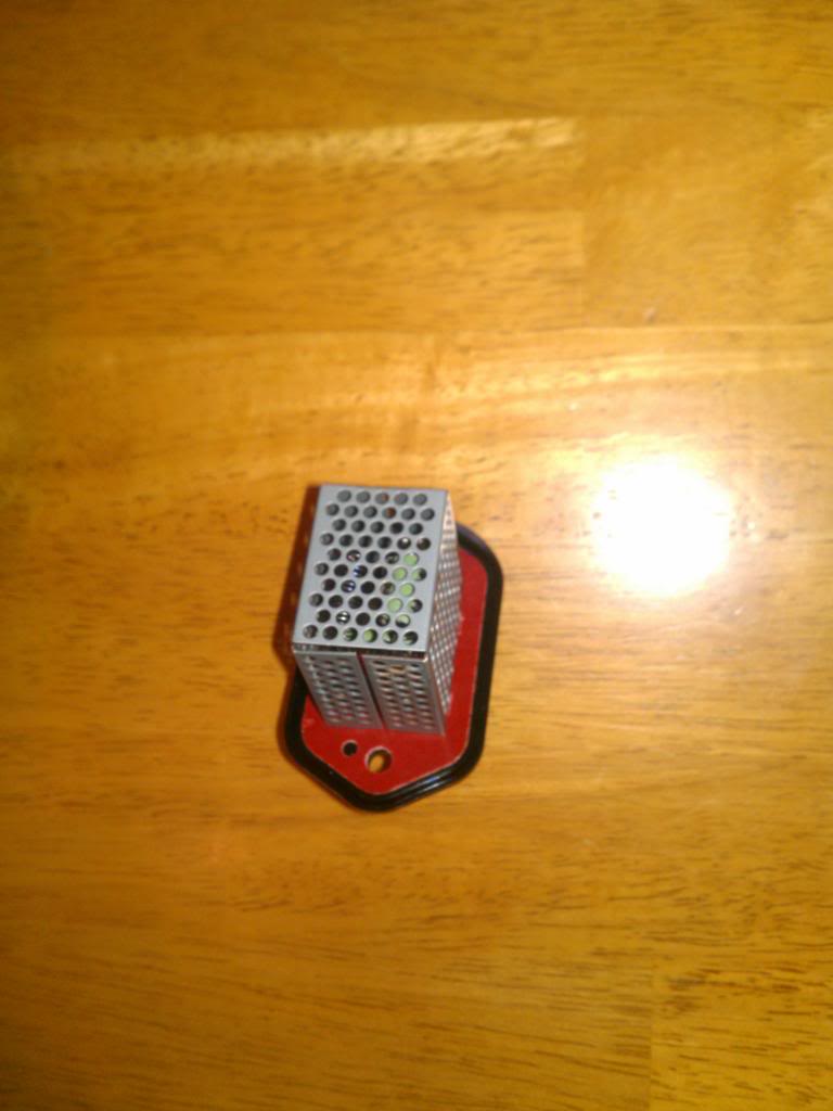
3. Now that we have the blower out we need to disassemble it:
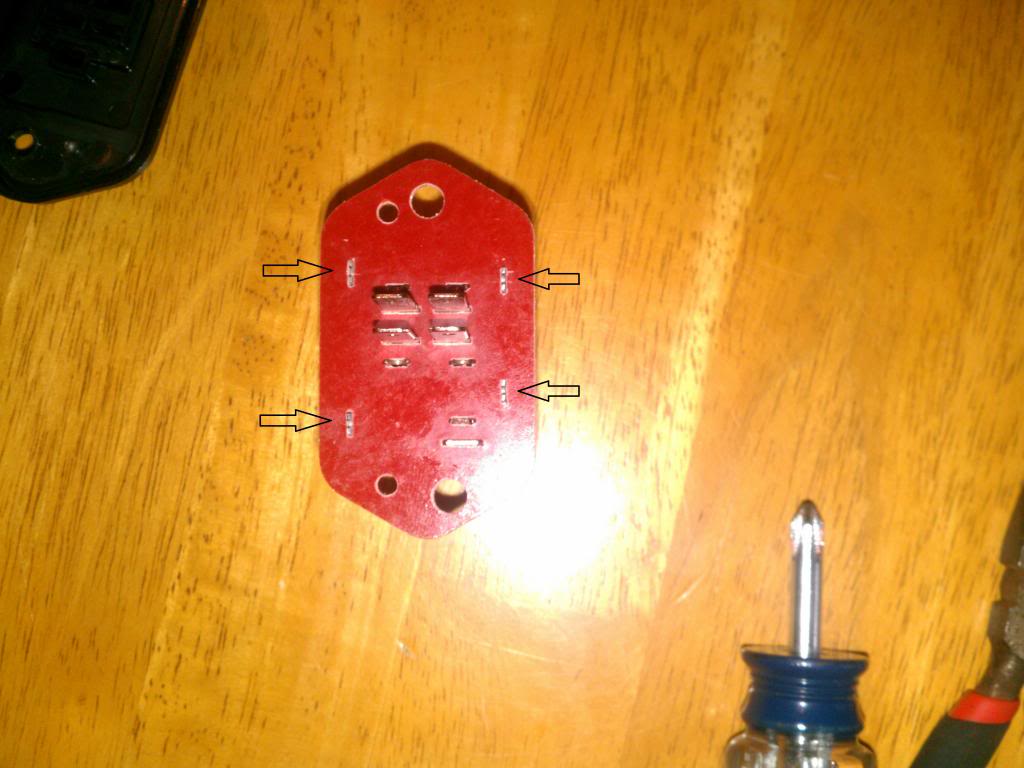
a. Remove/slide off the black plastic base
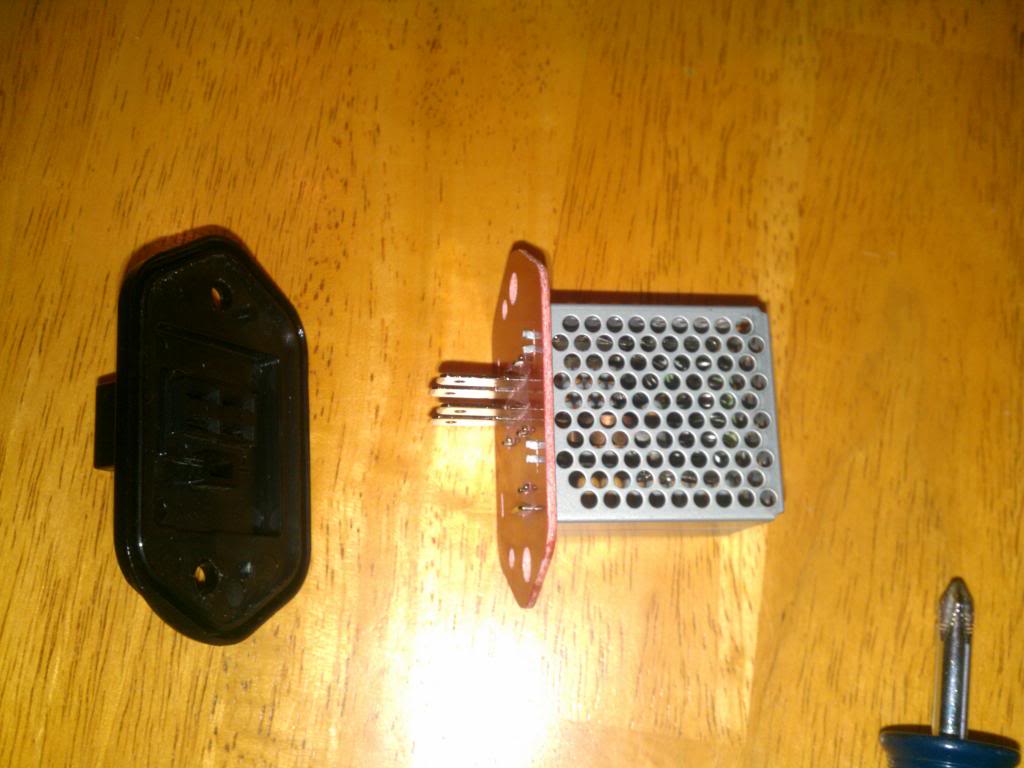
b. Pinch together the metal tips the hold the square metal screen housing and slide the housing off of the resistor (refer to the arrows).
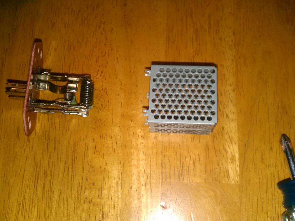
All slid off:
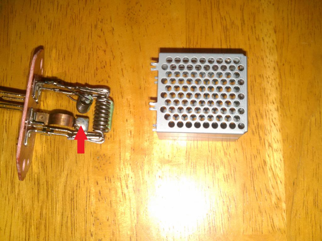
c. Now all you have to do is solder the copper filament which due to a poor soldering joint came undone. The picture below is after it has been re-soldered (refer to the red arrow) Note: you will need to hold the copper “filament” to the solder point because the “filament” is under slight tension.
d. Reassemble in reverse order of assembly Note: remember to bend the metal tips to secure the square metal screen housing as it was prior to disassembly.
Reassembled:
4. Install the blower resistor with the two screws, then connect the connector.
5. Reinstall the passenger’s dashboard undercover by pushing the pins and the clips securely into place. Replace any damaged clips.
Test out and confirm repair.ALL DONE!!!!!!
I thought I would make a DIY on how to repair the blower motor resistor on our generation Honda Fits (mine is a 2011). The symptoms of it being bad is the infamous HVAC fan speed control only working on 4 (high). I took the time to investigate the issue and it appears that poor soldering at one of the solder joints is the culprit more so than an excessive current draw from the fan (as stated in the TSB which addresses the issue). Well, it worked for me and no blower fan replacement was needed........
Repair Procedure:
http://www.underhoodservice.com/wp-c...0000057441.jpg
Fig. 1
1. Remove the passenger-side dashboard undercover (see Fig. 1):
a. Gently pull down the front edge to detach the clips.
b. Pull the cover toward you to release the pins.
http://www.underhoodservice.com/wp-c...0000057443.jpg
Fig. 2
2. Remove the blower resistor:
a. Disconnect the connector.
b. Remove the two screws and the blower resistor.
3. Now that we have the blower out we need to disassemble it:
a. Remove/slide off the black plastic base

b. Pinch together the metal tips the hold the square metal screen housing and slide the housing off of the resistor (refer to the arrows).

All slid off:

c. Now all you have to do is solder the copper filament which due to a poor soldering joint came undone. The picture below is after it has been re-soldered (refer to the red arrow) Note: you will need to hold the copper “filament” to the solder point because the “filament” is under slight tension.

d. Reassemble in reverse order of assembly Note: remember to bend the metal tips to secure the square metal screen housing as it was prior to disassembly.
Reassembled:

4. Install the blower resistor with the two screws, then connect the connector.
5. Reinstall the passenger’s dashboard undercover by pushing the pins and the clips securely into place. Replace any damaged clips.
Test out and confirm repair.ALL DONE!!!!!!
Last edited by zay2u; Aug 24, 2015 at 02:15 PM. Reason: fix dead links
Member

Joined: Nov 2009
Posts: 824
From: Atlanta, Georgia
Great DIY
But wouldnt it be easier to buy a new resistor from Bernardiparts for those of us without the Soldering iron to do this?
For those with the skills, you could charge a little bit for this repair and apply that green towards some mods!
For those with the skills, you could charge a little bit for this repair and apply that green towards some mods!
Thread Starter
|
New Member
Joined: Mar 2013
Posts: 5
From: Havre de Grace, MD
Well, it will always be easier to buy new, yet is more expensive and also take longer as you would have to wait on shipping. The purpose of this DIY (like most DIY) is to save money and time. Also, as for charging for the reapir I wouldn't because the forum is meant to spread knowledge and I feel I am doing my part to give back since other DIY/posting have helped me in diagnosing issues with my cars.

Member
Joined: Sep 2009
Posts: 382
From: Titusville, Fl
I can tell you from experience (I have a thread with a Y-T video) that a bad motor will drag, thus causing higher current flow. I pulled the old motor apart and saw just how poor the bottom support bearing is, and I compared the "free spin" properties of both the old motor and the new one. The new one was much easier to spin. Just saying...
Thread Starter
|
New Member
Joined: Mar 2013
Posts: 5
From: Havre de Grace, MD
I can tell you from experience (I have a thread with a Y-T video) that a bad motor will drag, thus causing higher current flow. I pulled the old motor apart and saw just how poor the bottom support bearing is, and I compared the "free spin" properties of both the old motor and the new one. The new one was much easier to spin. Just saying...
I am sure there are times when the fan is the cause of the resistor gone bad as well. It is good to have your input as the diagnosis on your car was thorough and varied from mine.......In my case my fan had no problem "free spinning" and hence I traced the problem to the resistor. Also, I do agree a fan with a failing bearing will draw more current and also cause the resistor to pop at the same solder joint as it is the weakest point. At a minimum though, the DIY at least allows you to save the money on the resistor by repairing it and only having to purchase the fan to complete the repair. By the way, did your fan at least make an audible noise when it was failing?


Member
Joined: Oct 2013
Posts: 201
From: PA
Excellent work in taking that resistor apart and repairing a bad connection!
The days of people fixing their cars have been mostly replaced by replacing parts. Its not always a bad thing to save time but I'm a third generation auto technician that learned from my family and some old timers in the first shop I worked in back in the mid 80s. The two guys that owned that shop were near retirement and came from a time when everything was rebuilt and hardly replaced unless there was no other choice. Those guys taught me to teardown starters, alternators, wiper motors or just about anything else electrical and rebuild them. All calipers, wheel cylinders and masters were rebuilt in house. We even made gaskets whenever we could before we would even consider buying them!
Anyway, enough of memory lane. Again, awesome job at fixing that component!

Member
Joined: Oct 2008
Posts: 161
From: USA
I know it's an old thread but I felt I had to post. Haven't been here in ages. After two years of driving around with the fan on "4" because I was too busy to do anything with it, I found this thread and did this repair. But with caution....
Be advised that the solder joint in question is linking two parts together that are DESIGNED to come apart due to buildup of excessive heat. The brass contact is a spring and under tension for that very reason - in the event of increased resistance the solder connection would get hot enough to soften and let the springy brass contact pull away from the rest of the resistor pack. It is a failsafe mechanism. Soldering it back with more solder than the factory used will result in the resistor pack burning up before the reinforced solder joint will fail. This could mean a fire.
I don't intend to leave this repair like this. I listened to my blower motor and heard an abnormal noise coming from the bottom bearing. I'll pull it and check the free spin of the fan rotor.
Be careful.
Thread Starter
|
New Member
Joined: Mar 2013
Posts: 5
From: Havre de Grace, MD
I know it's an old thread but I felt I had to post. Haven't been here in ages. After two years of driving around with the fan on "4" because I was too busy to do anything with it, I found this thread and did this repair. But with caution....
Be advised that the solder joint in question is linking two parts together that are DESIGNED to come apart due to buildup of excessive heat. The brass contact is a spring and under tension for that very reason - in the event of increased resistance the solder connection would get hot enough to soften and let the springy brass contact pull away from the rest of the resistor pack. It is a failsafe mechanism. Soldering it back with more solder than the factory used will result in the resistor pack burning up before the reinforced solder joint will fail. This could mean a fire.
I don't intend to leave this repair like this. I listened to my blower motor and heard an abnormal noise coming from the bottom bearing. I'll pull it and check the free spin of the fan rotor.
Be careful.
Be advised that the solder joint in question is linking two parts together that are DESIGNED to come apart due to buildup of excessive heat. The brass contact is a spring and under tension for that very reason - in the event of increased resistance the solder connection would get hot enough to soften and let the springy brass contact pull away from the rest of the resistor pack. It is a failsafe mechanism. Soldering it back with more solder than the factory used will result in the resistor pack burning up before the reinforced solder joint will fail. This could mean a fire.
I don't intend to leave this repair like this. I listened to my blower motor and heard an abnormal noise coming from the bottom bearing. I'll pull it and check the free spin of the fan rotor.
Be careful.
You make some valid points which in retrospect should have mentioned. In writing this D.I.Y. I assumed diagnosing/inspecting the if the blower motor was faulty was a given (hindsight is 20/20 I guess.....
 ). Regardless, if your blower is also bad; when you replace it the repair will be complete as the new motor will not cause the extra current draw (and hence no overheating).
 By the way, the audible sound you mention coming from your blower motor is a pretty strong indication something is wrong with it. Fortunately the price of these motors new are about $50-$60 bucks online (rockauto, eBay, etc) and swapping them out is relatively quick procedure.

New Member
Joined: Jan 2014
Posts: 10
From: Syracuse NY
Wahoo!
So two days ago I had the issue with this relay,, I just fixed it in 15 mins
I don't get on here often or have anything to contribute often but I really want to thank the author of this post for taking the time to post this it's super appreciated!!
I don't get on here often or have anything to contribute often but I really want to thank the author of this post for taking the time to post this it's super appreciated!!


Thread
Thread Starter
Forum
Replies
Last Post
valk97
2nd Generation GE8 Specific DIY: Repair & Maintenance Sub-Forum
164
Jan 9, 2025 05:06 PM