When you click on links to various merchants on this site and make a purchase, this can result in this site earning a commission. Affiliate programs and affiliations include, but are not limited to, the eBay Partner Network.
3rd Gen GK Specific Fit Engine Modifications, Motor Swaps, ECU Tuning Sub-ForumThreads discussing engine mods/swaps/tuning for the third generation GK Honda Fit.
There was one interesting observation I noticed when I went over a good amount of runs because my statement on torque didn't make sense to me. I looked over between 125-133 torque runs to see what the heck was going on with the torque numbers. Some where higher than others while the vast majority of my runs had low torque numbers. Here's what I found out.
ALL of my runs where I tap the gas pedal to get the rpm needle to jump up to it's power peak, my torque numbers were low. When I say 'low' I mean, my torque was 8-12lb-ft less than when I simply floored the car.
What I'm observing is that when I simply floor the car, I allowed it to travel the full rpm band, through the torque peak (4600rpm), up towards the power peak (6600rpm). Tapping the gas pedal allowed the rpm band to 'jump' over the torque peak to reach the 6600rpm power peak.
So for instance if I floor the car with my current setup, my peak torque may be 112lb-ft but if I tap the gas pedal going wide open throttle, I'd only see 104lb-ft.
I've never seen anything like this before but I'm perfectly fine by it. It allows me to go faster without any more 'peak' torque than stock. 'Peak torque' is the key word since I'm making a little more torque at the top end, which is in essence more peak horsepower. I hope all my rambling is making sense.
Yeah i guess thats weird and we really can say that the app is just really for reference and could not compete against actual dyno number. Lol
Now im waiting for your great exhaust test thread. Or do you have one already? Im kinda thinking of just using a cat delete/headers with the same ID as stock.
OT: dunno if there are dvantages on going bigger diameter for the exhaust if basically the car is stock.
Keep up on researchin man! You doin us a big favor!
There are a couple of threads in the exhaust forum. Here's a recap!
1) Installed a 2" Dynomax Muffler,
2) Installed 2.5" to 2.25" Resonator (B-pipe) to 2.25" muffler.
3) Installed 2" J's Racing Cat delete with 2.5" to 2.25" Vibrant Ultra Quiet Resonator, 2.25" Xcelerator Muffler then 2.25" Max Pro Flo muffler.
4) 2" J's Racing Cat Delete to 2" Shop B-pipe to 2.25" Vibrant Ultra Quiet Resonator, 2.25" Xcelerator muffler to 2.25" Max Flo Pro Muffler
5) 2" J's Racing Cat Delete to 2" J's Racing B pipe to 2" Max Pro Flo muffler
**This is my current setup**
6) Final setup will be 2" J's Racing Cat Delete to 2" J's Racing B Pipe to 2" J's Racing 50R Muffler. I'm waiting on this muffler to arrive. It hasn't shipped yet *2 Month wait* I'm at 1.5 months now.
Nothing was wrong with the 2.5" setup. It is just louder than I would like. For most people, I'd recommend just changing out the stock muffler to a 2" straight through. No need to go with the J's Racing B-pipe or cat deletes. The stock muffler doesn't have the best flow setup though. It is not straight through. A simple muffler change should be sufficient (or perhaps a Bisomoto Pulse Chamber pipe....or just a pipe period if that's your cup of tea).
Your header is built into your cylinder block. There is no header to change. Only the cat converter pipe, B pipe and muffler.
Last edited by Myxalplyx; May 18, 2015 at 04:44 PM.
There are a couple of threads in the exhaust forum. Here's a recap!
1) Installed a 2" Dynomax Muffler,
2) Installed 2.5" to 2.25" Resonator (B-pipe) to 2.25" muffler.
3) Installed 2" J's Racing Cat delete with 2.5" to 2.25" Vibrant Ultra Quiet Resonator, 2.25" Xcelerator Muffler then 2.25" Max Pro Flo muffler.
4) 2" J's Racing Cat Delete to 2" Shop B-pipe to 2.25" Vibrant Ultra Quiet Resonator, 2.25" Xcelerator muffler to 2.25" Max Flo Pro Muffler
5) 2" J's Racing Cat Delete to 2" J's Racing B pipe to 2" Max Pro Flo muffler
**This is my current setup**
6) Final setup will be 2" J's Racing Cat Delete to 2" J's Racing B Pipe to 2" J's Racing 50R Muffler. I'm waiting on this muffler to arrive. It hasn't shipped yet *2 Month wait* I'm at 1.5 months now.
Nothing was wrong with the 2.5" setup. It is just louder than I would like. For most people, I'd recommend just changing out the stock muffler to a 2" straight through. No need to go with the J's Racing B-pipe or cat deletes. The stock muffler doesn't have the best flow setup though. It is not straight through. A simple muffler change should be sufficient (or perhaps a Bisomoto Pulse Chamber pipe....or just a pipe period if that's your cup of tea).
Your header is built into your cylinder block. There is no header to change. Only the cat converter pipe, B pipe and muffler.
This is what I tried today, it was not good the throttle response was very slow and delayed, and for power a drastic decrease but was curious to see if I moved where the maf was if it would be beneficial at all, but tomarrow I'm gonna be trying something diffrent, this all thanks to the research so far from myxalplyx
This is what I tried today, it was not good the throttle response was very slow and delayed, and for power a drastic decrease but was curious to see if I moved where the maf was if it would be beneficial at all, but tomarrow I'm gonna be trying something diffrent, this all thanks to the research so far from myxalplyx
^^^That is a really nice looking intake Cleangd3! AEM prototype looks like that from what I saw. The delayed response may be due to the filter being over the transmission but I won't play expert here. It's all a learning experience.
^^^That is a really nice looking intake Cleangd3! AEM prototype looks like that from what I saw. The delayed response may be due to the filter being over the transmission but I won't play expert here. It's all a learning experience.
Thanks man I was suprised, I was like I'm gonna put this into production, then I didn't have any results lol so that's scraped now, but it is just experimenting and I plan on doing a little more till the car goes to ktuner for a tune next week.
In my never ending quest for the perfect intake and experimentation, I have an idea I'd like to share. First a little background.
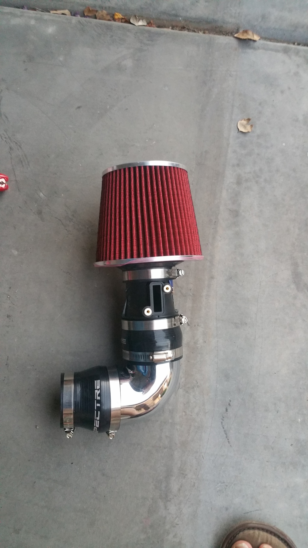
I had a couple of questions around an ECU reading that reads intake pressure and barometric pressure. Barometric pressure (outside air pressure) stayed at 14.6psi. I notice tiny changes in the intake air pressure when changing from my 'stock' intake to my Myxal SRI-CAI. With the stock intake (using HKS filter), at wide open throttle (WOT), I was seeing intake air pressure of 13.9-14.2. When I changed to the Myxal SRI-CAI, I was seeing 14.2-14.6psi of pressure in the intake. A tiny change...nothing to write home about but any improvement to me is an improvement. You can see a pic of the Myxal SRI-CAI on the first page.
So I asked myself, what If I could improve that 14.2-14.4psi at wide open throttle. What if I could bring it up to 14.5-14.6psi? What if I could get slightly over 14.6psi (yeah, yeah...we can wish right?).
So I was looking at the new HPS CAI in the video and how the piping is routed.
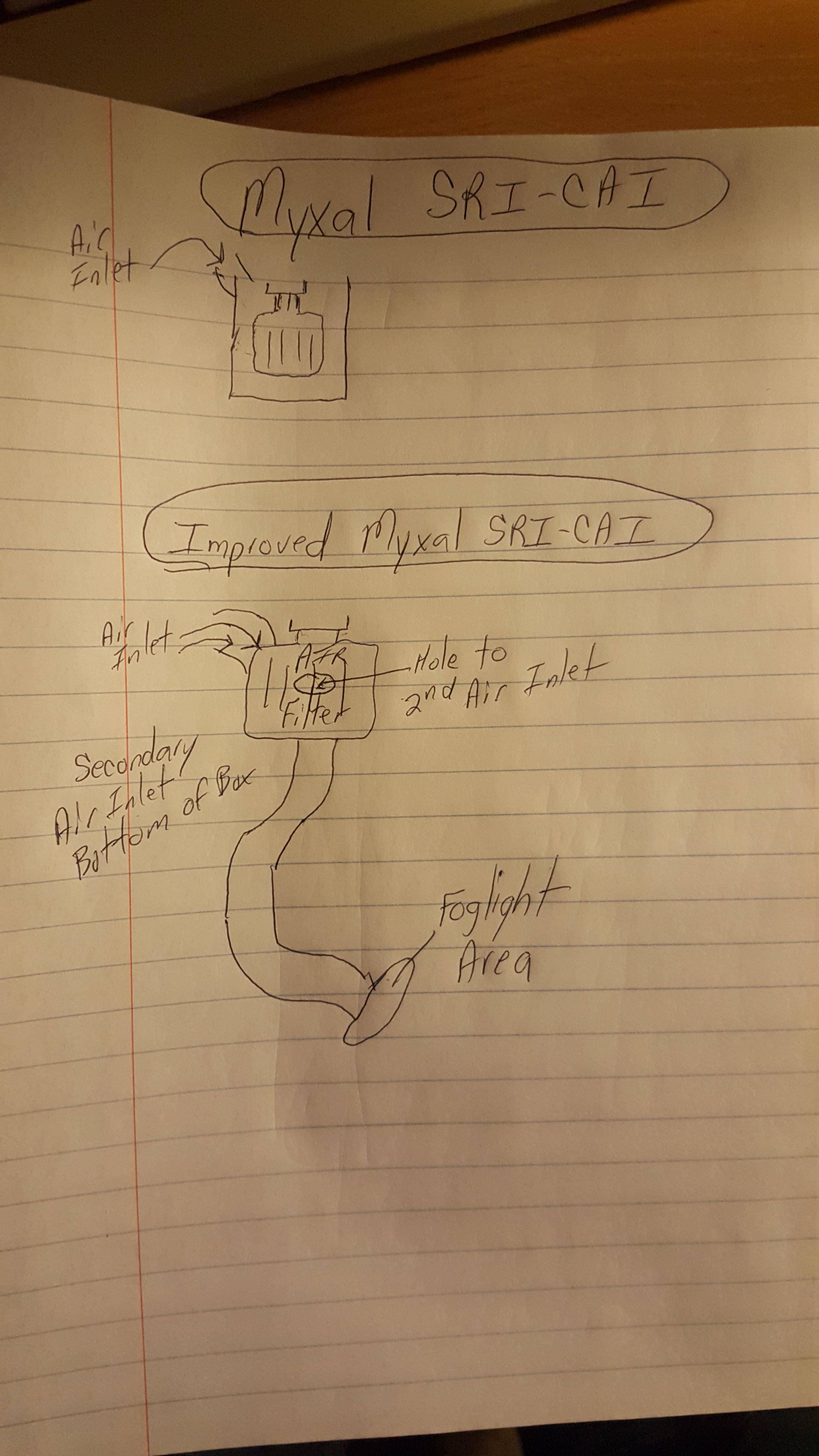
Although the Myxal SRI-CAI filter is really tight in the box, with the box touching the top, bottom and one of the sides of the filter, it performs well. However, I could cut a hole in the bottom of the filter box and route it to another cold air source. What would happen if I'd do this? Could the extra air coming in bring up the intake air psi slightly?
I'll be modifying the Myxal SRI-CAI with some tubing that will be routed like the HPS CAI, down to the foglight area.
I have some air horns lying around the garage that I can adapt to the box. I just need to get some ducting/tubing to route to the driver's side foglight. I may even be able to help force a little extra air into the box depending on how I have the tubing's inlet facing out. Both the foglight area and the top of the radiator are high pressure areas so at higher speeds, I hope to see some measurable differences.
^^^This is not the actual Myxal SRI-CAI box that will be modified. This is one of three I have lying around. I have one currently installed.
I'll report on my findings on if I see any changes and perhaps take a few more pics. Again, I'm not one to talk hypothetically on if this will work or not. I just do (see sig) and let the other folks discuss.
BTW: Here is an interesting article on what exactly I am trying to do. I came across this after posting. The manifold pressures tested are similar to what I saw stock. http://www.vararam.com/ramairinaroadcar.html
Last edited by Myxalplyx; Feb 25, 2016 at 03:24 AM.
Just a thought,, there are some programming things going on with the fly-by-wire throttle that you may be fighting. There is a ramp table that controls how fast and far the throttle opens in relation to the pedal position. If Honda is referencing the intake pressure to validate the TPS and Pedal position input that may be why your getting the split in torque numbers.
Just a thought,, there are some programming things going on with the fly-by-wire throttle that you may be fighting. There is a ramp table that controls how fast and far the throttle opens in relation to the pedal position. If Honda is referencing the intake pressure to validate the TPS and Pedal position input that may be why your getting the split in torque numbers.
Interesting point! I do still have my Sprintbooster that I previously had a problem with. I consulted Sprintbooster and they thought it was perhaps a loose connection because they said no-one else after me reported they had any issues. Never re-installed it though. I may be re-installing it and set it to a more aggressive throttle opening setting if that helps. I know the right way would be to change the ramp tables but re-installing the Sprintbooster would be the equivalent to an SAFC changing the air/fuel ratio between what the stock ECU tables would be setting the maf sensor at. What are your thoughts on that? Maybe I'm looking at this wrong.
Last edited by Myxalplyx; Feb 25, 2016 at 12:55 PM.
I think your right on, BMW's have the same issue with the 2005(ish) on cars, the Fly by wire has some weird off idle lag and a gadget is required between the pedal and harness to the ECU to make the car slam the throttle butterfly open all the time when you tell it to.
My BMW (2005 330XI) will throw a code if I try and run it without the air cleaner box connected. (Working the shop not driving.. ) but BMW has a crap ton more codes than Honda. (Not saying thats a good thing ) Plus the car "adapts" to your driving style. My wife drives the Bimmer most of time and every time I get back in it its running weird, she short shifts the darn thing all the time and most of her trips are around town. I have to rod the crap out of it for about 10 miles to get it to go up an on-ramp like I want. Takes about 5 hard pulls to reset the adaptions..
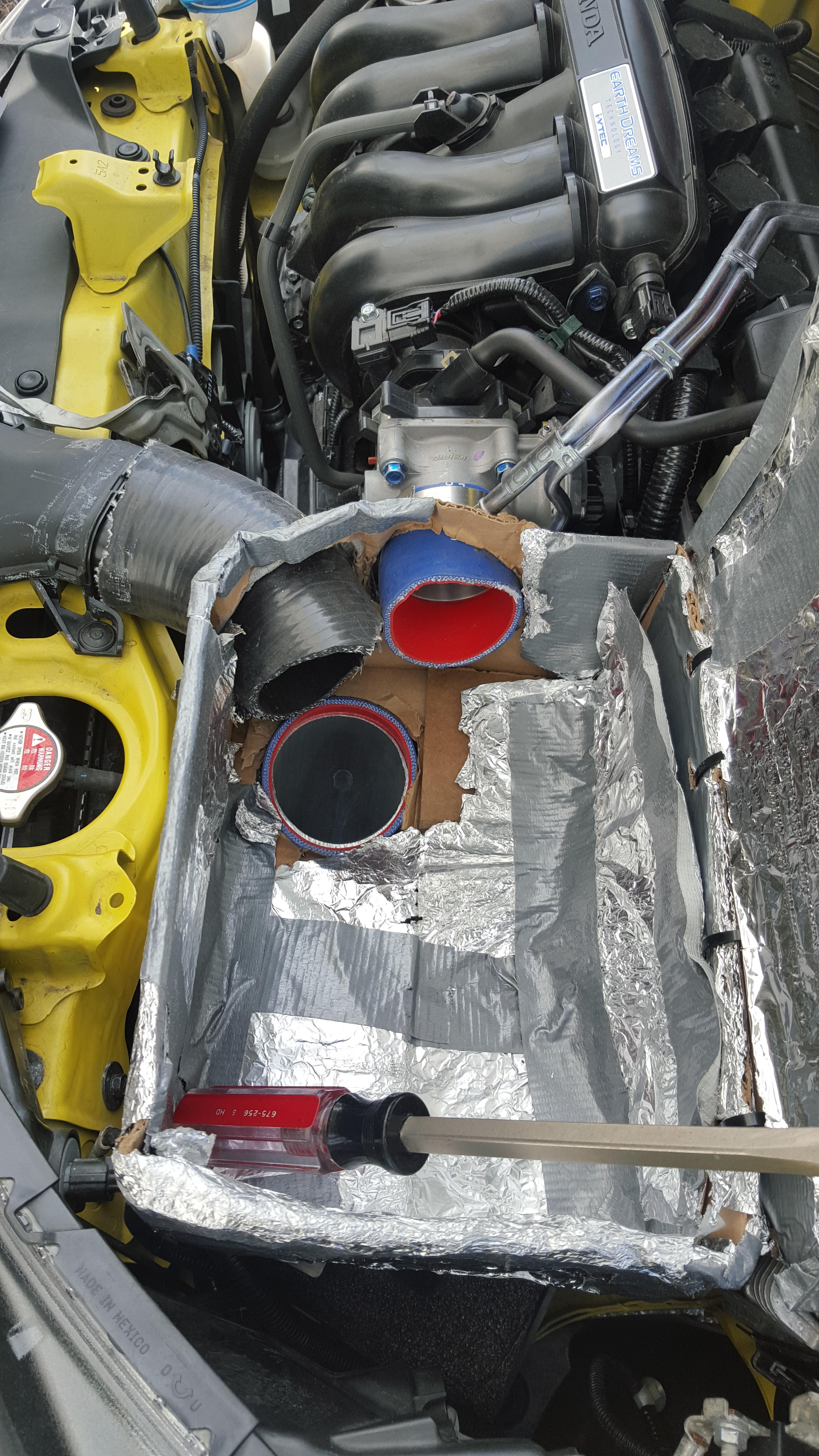
This looks like fun. Removed intake and battery and there looks like little to no room to get piping down there (Kudos to HPS). A rubber hose and the Helmoltz resonator container appears to be in the way. Even still, it doesn't look like a ton of room to work with.
Gonna have to see what I can do. The weather is sucking right now (Cold and Windy out) and my garage is already occupied.
This is looking from the driver's side wheel, through the wheel well area, towards the passenger side. This area is where you will see the HPS filter coming in at in the video above. It looks workable, a little bit. Will see if I can get two 90 degree pipes through this area. One 90 coming from the box to the hole. Another 90 (or a bend anyway) to connect the pipe to the foglight.
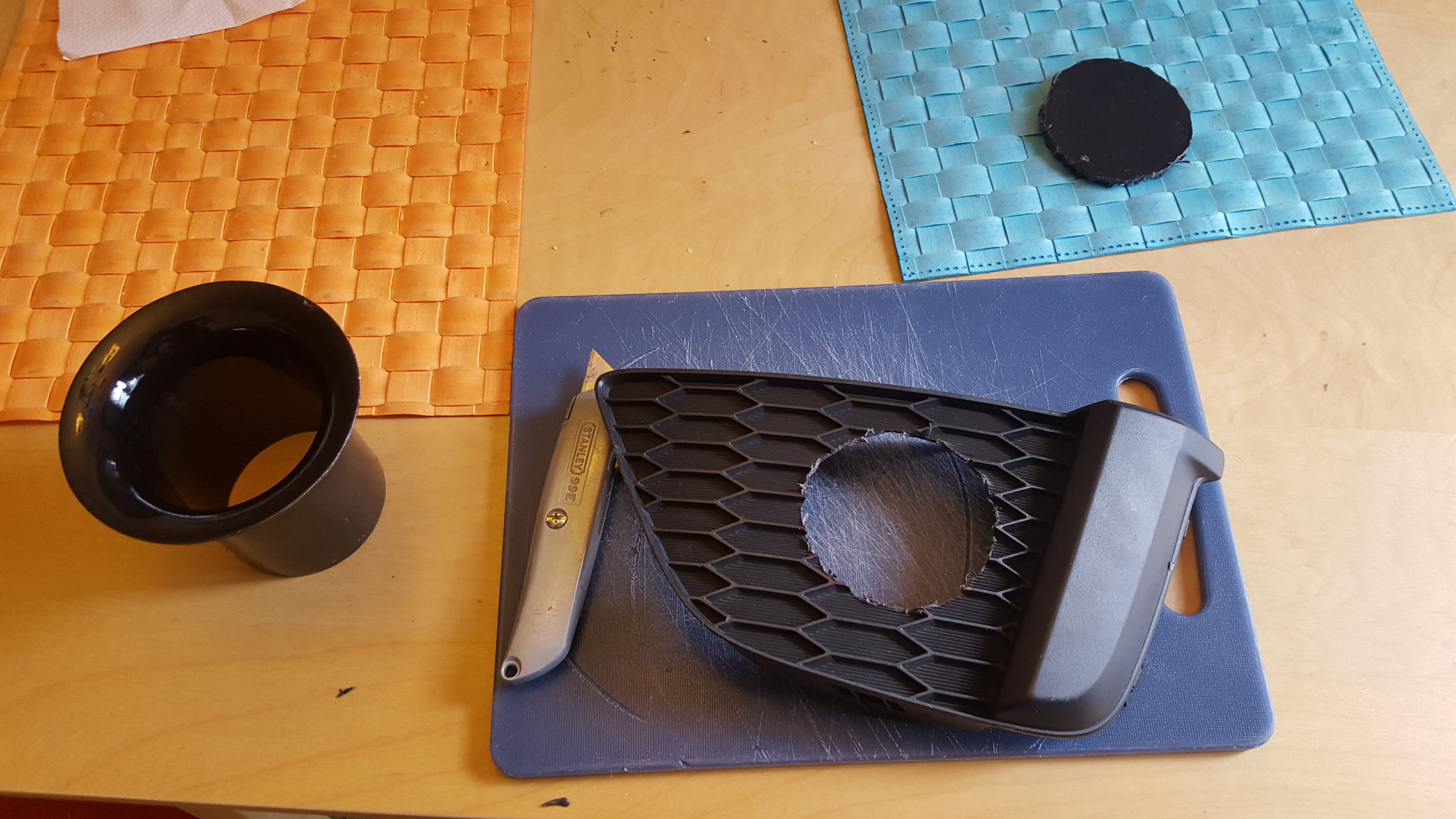
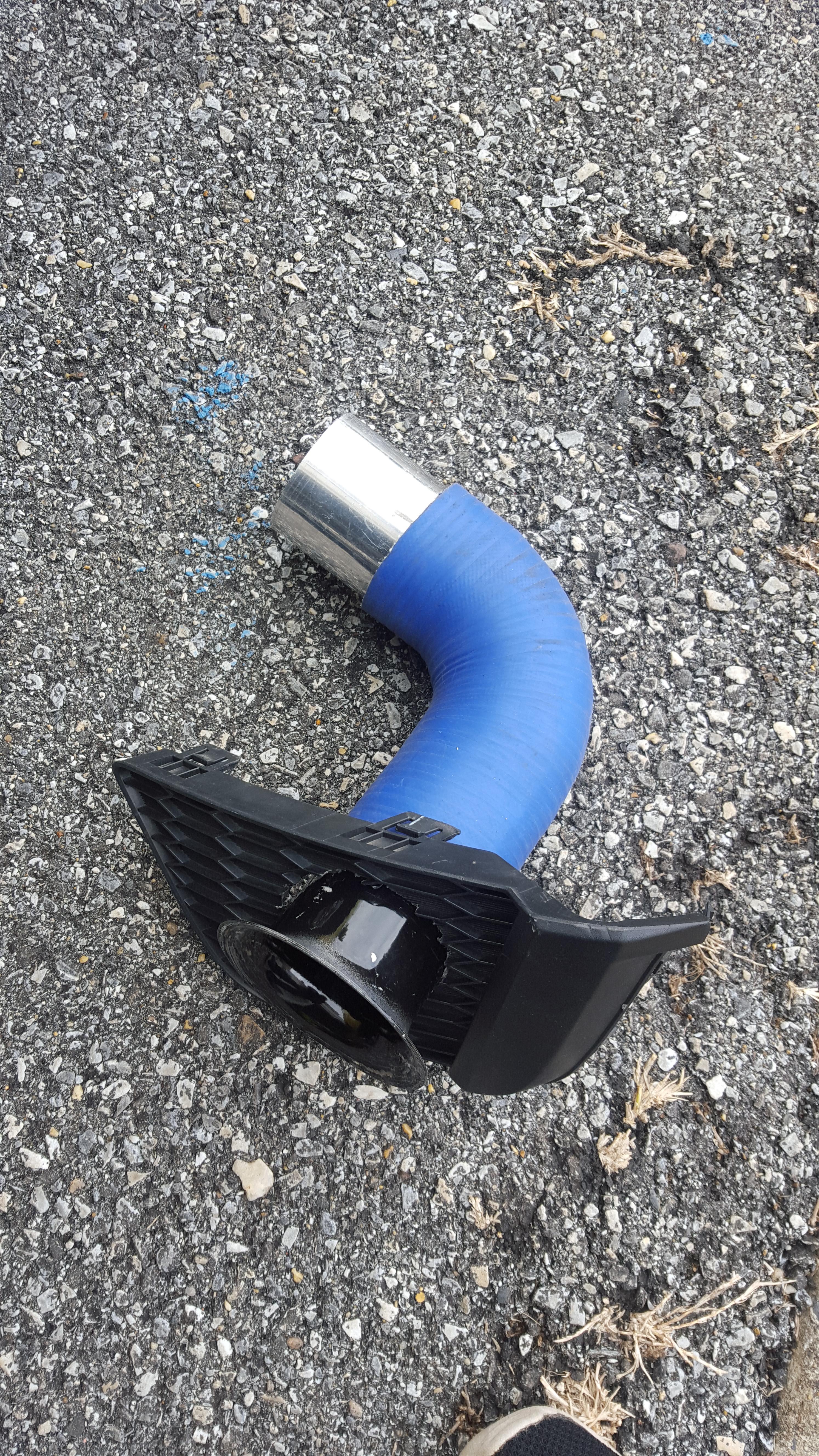
I found this in the garage. May be able to work with it. I will be ordering up a new foglight cover tomorrow. In the meantime, I'll cut a hole in this one and push this piece through. Once it is pushed through, I can connect a silicone hose to the backside of it with a hose clamp. The silicone hose will have to connect at an angle so the piping that connects to it can go straight through the opening you see above. I don't want this to look so obvious when I hook it up though.
Found some black Rustoleum paint way at the bottom of some boxes in the garage. I knew it'd come in use someday. Sprayed this down so it won't stand out so much. This is all experimentation, not show car material. Once it dries out by tomorrow, I'll connect it up and see if I can get some tubing to run back in front of the radiator to make this happen.
Fun stuff!
Last edited by Myxalplyx; Feb 26, 2016 at 09:49 AM.
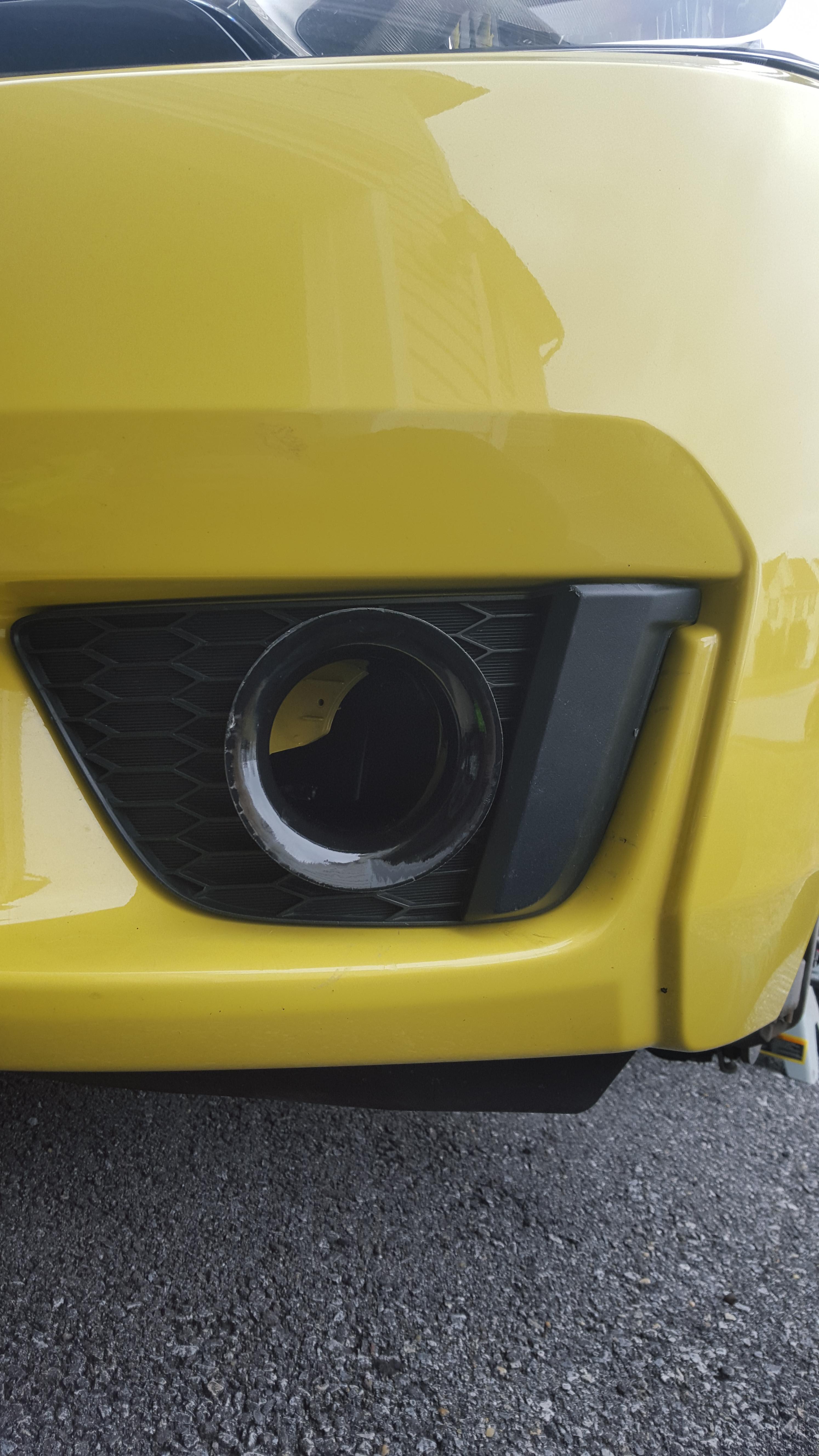
I am up bright and early this morning. This is a pic of the driver's side foglight before I butcher the plate piece that is in place.
I cut a hole in the foglight for the ram air piece to go into. The paint dried out overnight on it so it's no longer tacky to the touch.
Looks like a 'fit'! That metal piece in the back is screwing with how I want to connect to the air horn piece (Velocity Stack) though. I'm gonna have to think of a way to get around this. Gotta get this to work. Gonna hit up the garage to see if I have something to connect to the air horn. It's not a flush fit because if I do that, the air horn piece will be angled such that it will not fit through the hole properly. Kinda sucks but again, all of this is for function, not form. I wouldn't recommend anyone do this but I have a few screws loose. Ok...a lot of screws loose but who's counting?
Last edited by Myxalplyx; Feb 26, 2016 at 01:00 PM.
Found a 90 degree silicone piece in the garage. Put this together and it looks like it can work. Now for the straight piece to go up to the air filter box. Aluminum pipe or silicone hose? Hrrmmmm!
I ended up getting a 12" long silicone hose. Found a piece of 3" 180 degree aluminum pipe and cut it so that I could connect it to the hose and the other end to the air box. This is what it looks like. I cut a small piece of silicone hose and connected it to where the pipe enters the bottom of the airbox to make it seal a little better. I was wishing to have the 2nd ram air pipe go into this box at another location but I'll take what I can get. It's not a lot of room to work with here.
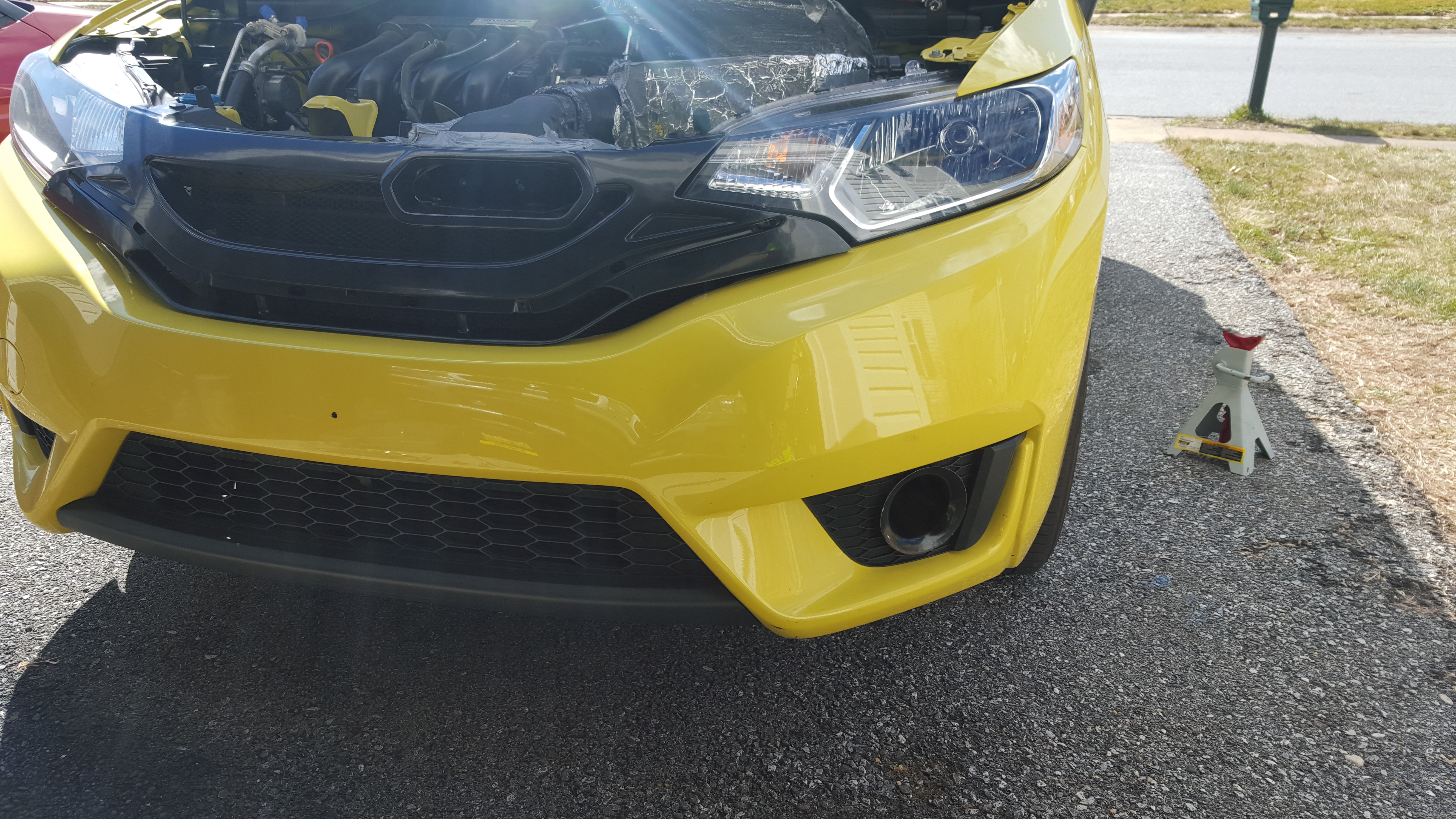
This is what the two ram air locations look like from outside of the car. One from the J's racing ram air grille and the 2nd from the driver's side fog light. I love doing stuff like this, I don't care how cheesy it is.
Will it work? Who knows! Who cares! This is all in good fun. Live and learn! The goal is to see if I can increase the intake psi even slightly. Currently it bounces back between 14.2-14.4 during wide open throttle. Even with no increase but a steady 14.3 or 14.4, I'll take it as success. I can't see how it will be worse. The intake is all buttoned back up and duct taped at all openings to try to seal the air in as much as possible (and keep heat out). I'll report back. Fun stuff!
Last edited by Myxalplyx; Nov 15, 2020 at 10:10 PM.
You might consider cutting out the whole textured area, replace it with a black mesh then attach the horn to the back side of the mesh with Black tie wraps, if you size the mesh about 12mm it should be kinda stealth and the intake won't suck up anything too scary..
Found a 90 degree silicone piece in the garage. Put this together and it looks like it can work. Now for the straight piece to go up to the air filter box. Aluminum pipe or silicone hose? Hrrmmmm!
I ended up getting a 12" long silicone hose. Found a piece of 3" 180 degree aluminum pipe and cut it so that I could connect it to the hose and the other end to the air box. This is what it looks like. I cut a small piece of silicone hose and connected it to where the pipe enters the bottom of the airbox to make it seal a little better. I was wishing to have the 2nd ram air pipe go into this box at another location but I'll take what I can get. It's not a lot of room to work with here.
This is what the two ram air locations look like from outside of the car. One from the J's racing ram air grille and the 2nd from the driver's side fog light. I love doing stuff like this, I don't care how cheesy it is.
New intake is here. I will call it the--->
***Myxal Dual Ram SRI-CAI***
Will it work? Who knows! Who cares! This is all in good fun. Live and learn! The goal is to see if I can increase the intake psi even slightly. Currently it bounces back between 14.2-14.4 during wide open throttle. Even with no increase but a steady 14.3 or 14.4, I'll take it as success. I can't see how it will be worse. The intake is all buttoned back up and duct taped at all openings to try to seal the air in as much as possible (and keep heat out). I'll report back. Fun stuff!
Hello,
On the pictures above I see that the pipe from the grill and the pipe from the fog light meet at the same point and 90degrees (Perpendicular) to each other.
I imagine that both air flow would heat each other and the stronger one would block the other,
similar in principal to air curtain...
If you could move one pipe further so they won't exit at the same point,
that might actually flow even more air.
imagine you had two garden water hose and firing at 90degree with each other and separate them and let them had their own path.
even better if the hose from the fog light could exit right at the bottom of the cone air filter so the lower surface of the cone can absorb all the incoming air from the bottom hose while the rest of the cone area will absorb the air coming from the grill hose...
I think... I might be wrong
but I can truly relate how fun it is to create special one of a kind project like this.
even better if the hose from the fog light could exit right at the bottom of the cone air filter so the lower surface of the cone can absorb all the incoming air from the bottom hose while the rest of the cone area will absorb the air coming from the grill hose...
That is EXACTLY what I wanted to do. With how tight that area is, that hole was the only place I could get the hose/piping to enter the box. The location that you speak of has the battery sitting underneath the box. That would've been ideal though. The side between the airbox and the firewall has some space there but it would need it's own air feed source and the piping feeding the box would be over the transmission. It can be done but the battery tray would have to be removed. I started to do that but changed my mind and decided I may try something like that at another time.
Yeah....I'm right there with you. Couldn't find a way to do it. There's always another day though. Thanks for the suggestions guys. The wire mesh isn't a bad idea either.
Actually, after testing this out, I may do another weird project. The PRM air filter splitting off into both of the foglight and the grill opening. Just to see what it does and how it performs. I'll actually be looking for a large 'Y' silicone hose next week to test this out. Just because!
Did a couple of runs tonight. Everything seems all over the place.
**Deleted a bunch of info **
I just need to take it to the track to do some tests. Track was closed tonight because it was 'too cold'.
In all honesty, I'm just ready for a tune. Need a tune! Larger maf sensor is only a 5 minute install away. These little engines want to BREATHE.
Last edited by Myxalplyx; Feb 27, 2016 at 02:28 AM.
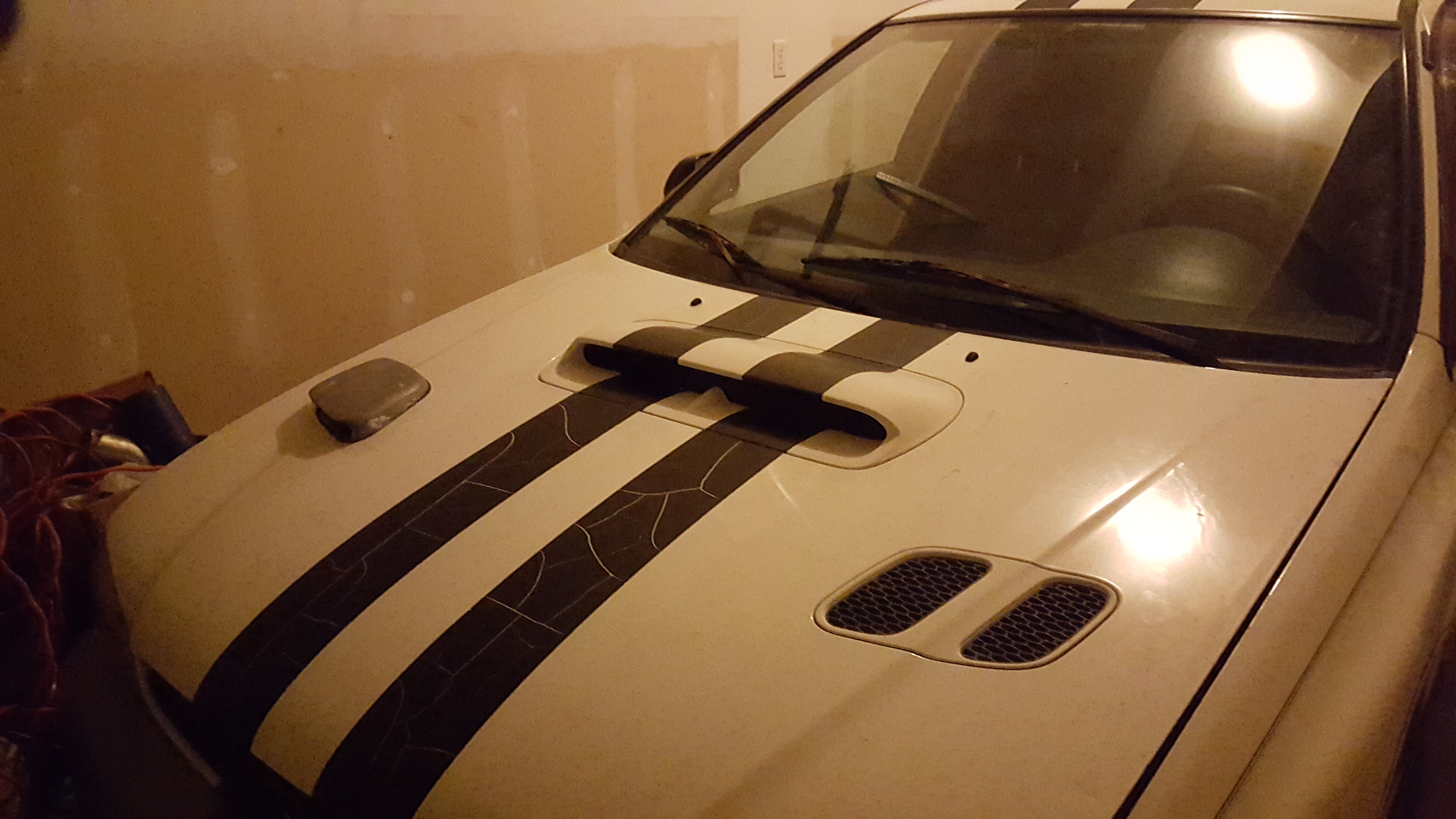
Anybody ever tried a subaru hood scoop to solve this puzzle?
This is my baby that's in the garage now.
NOOOooo! That's a bad idea. You have been cursed for even suggesting it. I know I can just get another piece but convenience is king. I stopped looking at it so I'm cool now.
BTW: My mind is always racing at 1-3am in the morning. I'm currently researching how to build an airtight intake box. If anyone have any ideas, please feel free to chime in. I'm listening! I can't sleep anyways. Here is where I'm starting at now ----> Building and Testing an Airbox
Last edited by Myxalplyx; Feb 28, 2016 at 01:40 AM.


 I hope all my rambling is making sense.


 I know I can just get another piece but convenience is king. I stopped looking at it so I'm cool now.