When you click on links to various merchants on this site and make a purchase, this can result in this site earning a commission. Affiliate programs and affiliations include, but are not limited to, the eBay Partner Network.
3rd Gen GK Specific Fit Engine Modifications, Motor Swaps, ECU Tuning Sub-ForumThreads discussing engine mods/swaps/tuning for the third generation GK Honda Fit.
Anybody ever tried a subaru hood scoop to solve this puzzle?
I've thought about this quite a bit. I'm not sure how the air is entering/leaving the engine bay. I doubt a subie scoop will increase intake velocity, but is could help reduce the parachute effect of the engine bay.
I think it is possible the fog light area is a stall zone and it might not be the best location for intake. There might be some possibilities by removing the plastic fender liners. It needs some fender vents too.
Another thing to consider is removing the rear fake bumper vents. I think the rear bumper acts like air brake. Removing the vents might reduce wheel well pressure a produce higher trap speeds.
I've thought about this quite a bit. I'm not sure how the air is entering/leaving the engine bay. I doubt a subie scoop will increase intake velocity, but is could help reduce the parachute effect of the engine bay.
I think it is possible the fog light area is a suction zone and it might not be the best location for intake. There might be some possibilities by removing the plastic fender liners. It needs some fender vents too.
Another thing to consider is removing the rear fake bumper vents. I think the rear bumper acts like air brake. Removing the vents might reduce wheel well pressure and produce higher trap speeds.
I guess my point is that all of these aero mods intended to increase intake airflow could be counter intuitive if they're placed in an area that doesn't have good flow, or the increase in overall drag requires more power to overcome than is being added by the intake mod itself
Another thing to consider is removing the rear fake bumper vents. I think the rear bumper acts like air brake. Removing the vents might reduce wheel well pressure a produce higher trap speeds.
After reading this thread and a few others like it, the main thing the guys spoke of is preventing air from getting up under the car to the rear bumper area was more worthwhile. BUT if you want to keep the air from the rear bumper, it'd be best to fill it up with something vs putting holes in it (Or removing the foglight covers in our case). Either way, no-one had did any tests around this. It was all just hearsay....which I hate. In our case though, it can't hurt. All we have to do is simply remove it. I'll give it a try.
Originally Posted by jhn
I think it is possible the fog light area is a stall zone and it might not be the best location for intake. There might be some possibilities by removing the plastic fender liners. It needs some fender vents too.
After reading your post, one article on this is from Autospeed -->AutoSpeed - More on Siting Cold Air Intakes
Last night, I specifically was looking for what areas on the front of the car have the lowest/highest air pressure. All cars are not created equal but something to go on is better than nothing. Look at a couple of these pics on a Lexus.
Applying this to the Fit, Honda did a nice job on the air inlet as that should be a high pressure area. The foglight area doesn't seem that far behind. It can be either the highest air pressure or just high, as long as the light isn't to far on the corner/bend. If an air horn is installed at the foglight (as in my case) you may be able to angle it slightly inwards to take advantage of any air bouncing off the front of the car towards the side. Maybe! It's worth a try.
The article is a nice read. (I love reading Autospeed articles) Their series titled, 'Negative Boost' is good.
Last edited by Myxalplyx; Mar 1, 2016 at 02:30 PM.
You can occasionally find a Magnehelic Pressure meter for sale.
1/8 in tube and run it to where you want a pressure reading then drive,
I've used plain old duck tape to hold the tube to the body.
You can occasionally find a Magnehelic Pressure meter for sale.
1/8 in tube and run it to where you want a pressure reading then drive,
I've used plain old duck tape to hold the tube to the body.
Wondering where you'd bring the hose through the firewall for testing though. Other than that, sounds good.
Keep the ideas coming! Thanks! I'm going to be testing the intakes at the track to get some real world numbers, if the weather holds out.
The dual intake to the box is complete though. I just took apart, secured and reassembled the fog light pieces for the fifth time. Everything is snug! The car does feel better. Seems to rev freer and faster but who gives a shi*. I don't believe in the feelings. It may actually be worse.
Meanwhile, I didn't want to leave the old PRM intake alone so I thought, 'what if' you can make a dual PRM intake that branched off into two feeds. What could that do? Possible benefits? Has it been done? I've searched and couldn't find anything.
So.......since I have the dual pipes coming close to each other, I need an item to make them merge together into one pipe. So now I'm looking for something like this ---> http://www.frozenboost.com/intake-pi...er-p-8190.html
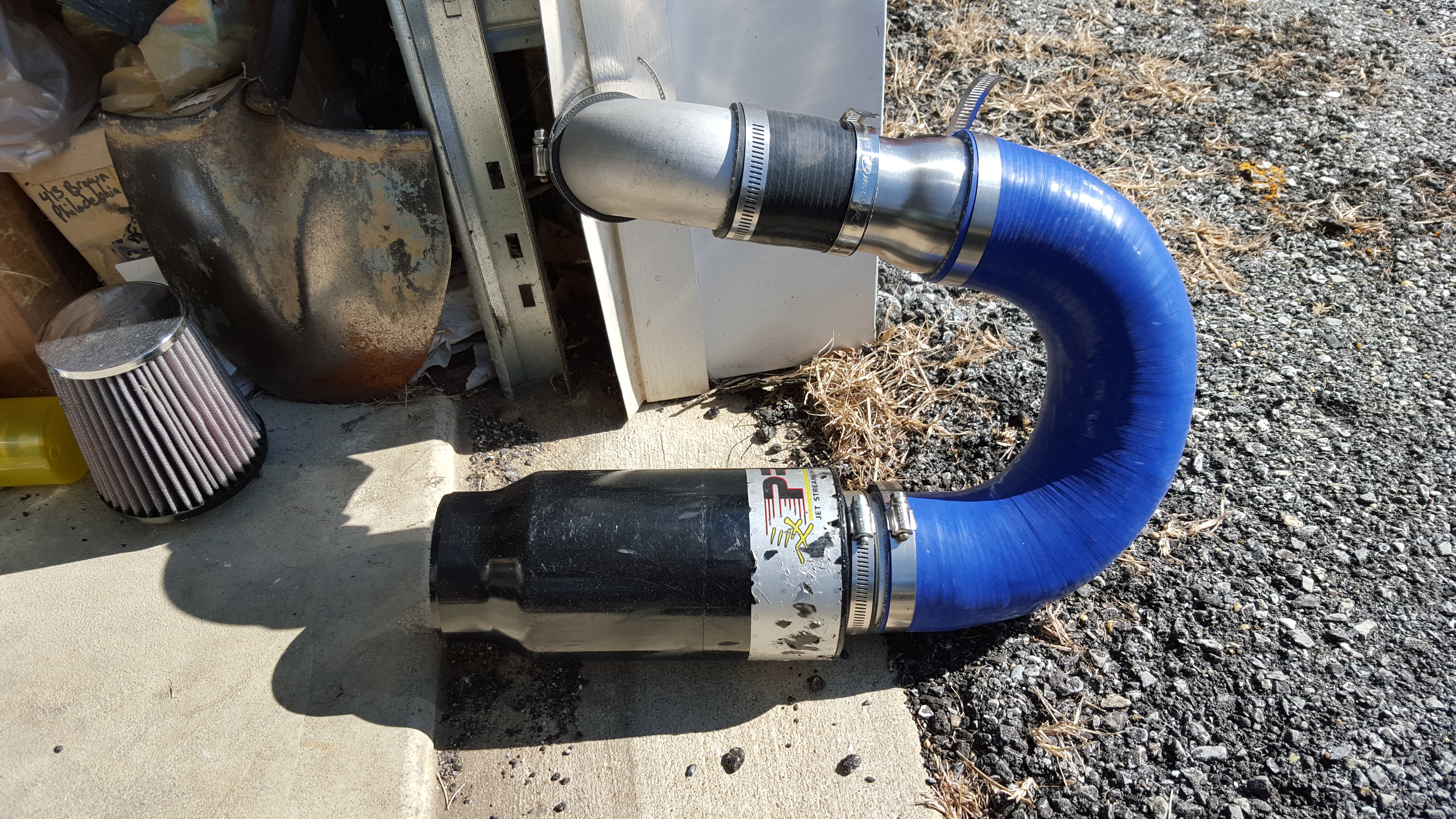
Here's my PRM intake that is sitting in the garage.
Unlike the new Weapon R intake, my PRM piping diameter starts at 2" at the maf sensor to a 2.5" 90 degree pipe. Then that pipe expands again to 3" before hitting a 180 silicone bend. Then 3" to the PRM air filter. I think a design like Weapon R and HPS, that has what looks like the same diameter pipe as the maf sensor, will choke off top end but be good for low and midrange. That's not to say that I think they are a bad design. I mean..that's Weapon R and HPS right? My focus is topend and I believe wider piping fits the bill (Or no piping at all, just a filter on the maf sensor and maf sensor on throttle body). So you can see, I am looking to hook up the 'Y' silicone hose to the PRM filter and have both dual rams feed the hose.
I'm going to take a trip down Verocious Motorsports warehouse to see what they have in stock.
**Update** Verocious Motorsports didn't have the part. So I ordered a 2X2.5" to 3.5" silicone 'Y' pipe from Frozenboost.com (Link Above). Will see how it goes...
Last edited by Myxalplyx; Mar 3, 2016 at 01:49 AM.
The Weapon-R intake does come with a flex pipe and velocity stack for connection to the cone that I'm likely going to put in this weekend at the same place your looking at Myxalplyx. It will run very close to what the HPS looks like. I'm not thrilled with flex piping, but it may prove to be better than what I'm running currently.
Don't use rubber/silicone hoses to carry pressure, use metal. The rubber hoses WILL eventually burst. Especially "T" and "Y" sections. The rubber should be limited to reinforced junction flex segments. The metal flows better as well and you can with a little skill make any shape you need.
You don't run the tube through the firewall you just tape it to the side of the car .. tuck it where it needs to go. I use the 1/8 inch semi rigid air line from napa. Its used to plumb air lines on some trucking applications and to plumb ice makers, uses simple press fit fittings. The hole is not posted at the air stream it just needs to be in the pressure zone you wan to measure. Aero effect starts at about 25 and is exponential as speed increases.. Most mag gauges have a tell tale that will show the highest reading attained.. A carb sync bourbon tube setup works too. Use WATER not mercury for this purpose. (Inches of water is how most of the is measurement is done.. )
Last edited by dwtaylorpdx; Mar 3, 2016 at 05:49 PM.
Had a small problem this morning. The Misses noticed that the battery was not getting charged properly. I never had a problem with the small Ballistic Evolution battery before. The terminals were on secure, it seems. So I had to put back on the stock intake.
While putting back on the stock intake, the small part that used to have the Helmholtz resonator hooked up to it is now resting inside the pipe that leads to the foglight. So it not only draws in air from the front grille but the foglight as well.
Interesting! This is an approach for those that are more conservative in their modding. So now I'm utilizing an HKS panel filter with cool air coming into the intake from two different locations. Wasn't planning on this but what the hell. Guess we'll go with this and test this at the track as well.
Last edited by Myxalplyx; Mar 3, 2016 at 01:48 AM.
It's 2am...brains at it. So...thinking on Acoustic Resonance! I'm talking about the AEM intake that made the 'AEM HUMP' in the power band from the old school Honda intakes. Do ya'll think the longer tubed HPS intake and/or the Weapon R may do this as well?
Here's some info on acoustic resonance. index
"Acoustic resonance:
Sounds are waves in the air, specifically longitudinal waves. These type of waves cause pressure waves (90 degrees
out of phase with wave itself) that are directly proportional in strength to the amplitude of the sound wave. It is
possible to utilize this effect to increase intake air pressures within the intake tube. In most instances the
amplitude of a sound wave is not that large. During resonance however the sound wave amplitude becomes much larger
(and so does the pressure wave following it). During this resonance it is possible to gain significant amounts of
torque and actually create positive manifold pressure (above 1 atm). This effect is sometimes called the AEM HUMP,
where power spikes ~10hp for a couple hundred RPM around 4500 RPM in their cold air intakes. The resonance frequency
of a pipe depends on the length and the diameter of the tube.
Fn= n (v/4L)
n = wave number, v = velocity of sound (~340m/s), L length of pipe
Note: v the speed of sound changes with temperature.
The diameter of a pipe has a small effect on the resonance frequency as well. The sound wave behavior remains consistent
with that of a pipe for ~.6 times the diameter (D). So
Fn= n (v)
___________
4(L+.6(D))
For a 1-meter intake pipe this translates into a resonance frequency of 85 hz or 5100 RPM. The intake pipe reaches
resonance frequency when the driving force of the system (the engine) is also at that frequency. This is RPM/60;
rotations per second."
So...what if (I ask myself this a LOT)....what if you split that piping into two. You have one longer pipe than the other. Could you possibly benefit from two smaller waves making two separate bumps in the powerband? I am thinking on this with the PRM intake that will split off into two paths.
Any thoughts from any physics majors here? I haven't found anything on the net talking about two separate paths coming into one. Yeah..I'm nuts I know. It's how I think though. I know a large part of this is controlled by different manifold sizes but that's outside the scope of my capability right now. Also, I haven't had any luck with discussing manifold upgrades with a few vendors a few months back.
Last edited by Myxalplyx; Mar 3, 2016 at 02:10 AM.
It's 2am...brains at it. So...thinking on Acoustic Resonance! I'm talking about the AEM intake that made the 'AEM HUMP' in the power band from the old school Honda intakes. Do ya'll think the longer tubed HPS intake and/or the Weapon R may do this as well?
Any thoughts from any physics majors here? I haven't found anything on the net talking about two separate paths coming into one. Yeah..I'm nuts I know. It's how I think though. I know a large part of this is controlled by different manifold sizes but that's outside the scope of my capability right now. Also, I haven't had any luck with discussing manifold upgrades with a few vendors a few months back.
My thoughts on this? The likelihood of being able to create the correct, sympathetic intake volumes to get any gains out of this, without significant testing and modifying, is HUGELY unlikely. All of the information and explanations I've been able to find are on sound acoustics (like how Bose does what it does) and that it take TEAMS of very smart people to get things right. For my purposes, I'm keeping things as simple as possible on the intake side. Calculating fuel to air requirements, flow restrictions, etc is possible, but I give you mad props for attempting this. Be sure to keep us up on your results.
If I were you, I would just concentrate on getting the most straightest path possible
with the largest opening possible to collect as much air as possible and ram it into the airbox.
Which mean getting as large scoop as possible around the grille area to collect as much air there and channel it as straight as possible to pressurized the airbox.
I think,...
The air coming from the fog light got to pass right angle bend that it would
reduce the ram effect too much to be effective...
I did and completed that! That's why I purchased the J's grille vs the stock grill that had no opening there. The air still hits a 'wall' and have to go up before going straight towards the air filter again. I'm just testing 'new' stuff just for the sake of it. I haven't seen anyone else doing anything like it on the net. It may be a waste of time but what if (Here I go again) it just happens to make things better? This is what I discovered while testing my increasing diameter CAI on my RAV4 at the track. I'll never make a one diameter cold air intake again after that.
Your point about the foglight is valid. I think the same way as you do. Something weird is going on with that extra air being fed into the box though. Weird = Seems Better! Maf g/s spiking up to 111g/s vs the 108g/s I had before and air/fuel ratio hanging at 12.7-12.8 vs the 12.5-12.6 (Peak) that I normally get with the standard CAI. Gotta do more testing! Hoping to see someone rig a foglight setup to their stock intake and test it out that way (Like what I'm doing now). Rather hear someone else's opinion on this.
Wanted to share some thoughts that are obvious to some and not so obvious to others. Take a look at this picture I took ->
On the left if the stock air filter. It's pretty clean because I hardly ever used it. Next to it is an HKS panel filter. It's ghetto rigged because I cut the filter into the square shape you see but it fit and worked. To the far right is an S&B cone air filter.
Now think about your engine sucking air through the air filter. The square shaped filters have only the square shape for the air to go through. The HKS filter probably has bigger 'holes' in it for the air to go through which would help your engine breathe a little easier. The cone shaped air filter has a lot more area for the air to go through all around it and on top of it. This is one reason why it is effective at making more horsepower (And perhaps bigger 'holes' in it too for more air to go through).
Here's another look at the cone air filter vs the stock panel filter.
Now imagine if I were to wrap that stock panel filter around that cone air filter. It'd be lucky if it were to go around half of the air filter (without stretching the stock air filter). That's how much extra air is available to go through the cone filter vs the stock air filter. It's good to see this visually so some people will understand the difference.
Some may argue that the stock panel filter is fine for the engine and is capable of breathing in what the engine is capable of sucking in at WOT without any restriction. You have no argument from me but feel welcome to debate with others on the forum. I only test and let the results speak for itself.
I have a habit of testing things at full throttle and wanted to look at intake air pressure while the car is at idle today. Was comparing what the stock air filter, the HKS air filter and the Myxal SRI-CAI filters intake air pressure looked like at idle. Was just curious, hence the pictures. I'm still looking things over but there is a difference. I have to look a lot more before saying anything on it.
Last edited by Myxalplyx; Mar 4, 2016 at 12:05 PM.
Dont know if you've played at all with it, but a standard GM MAP sensor can be used with a VOM to see relative pressure. It just needs 12V ground and then has the sig out wire..
If you buy the right one it will do neg or positive pressure..
Dont know if you've played at all with it, but a standard GM MAP sensor can be used with a VOM to see relative pressure. It just needs 12V ground and then has the sig out wire..
If you buy the right one it will do neg or positive pressure..
I haven't! Interesting! Will have to look into that.
BTW: I didn't ignore you about not using silicone for pressure. If this was supercharged/turbocharged, I'd take precautions.
On another note, the 'Y' piece came in today. WAY quicker than I thought it would. I just ordered it. Wow...that's service! Thanks FrozenBoost.com!
Maybe midday or tomorrow night, I'll take the stock intake apart and try to get some pieces together from the garage or basement to make this work. We will see!
Last edited by Myxalplyx; Mar 4, 2016 at 07:10 PM.
Totally agree with extra surface area..
On the left is K&N filter for stock OEM CRZ airbox that I previously used,
On the right is K&N filter for Mugen CRZ airbox that I currently use.
Nice work and intake, I am working on something similar, but on a city redneck version. First I did the AEM intake and can tell right away a grab to the acceleration. Then I added the HKS HP-E and can tell a smoothness up surge.
Totally agree with extra surface area..
On the left is K&N filter for stock OEM CRZ airbox that I previously used,
On the right is K&N filter for Mugen CRZ airbox that I currently use.
Wow! That's just about twice the surface area. Excellent choice!
Originally Posted by atvfit16
Nice work and intake, I am working on something similar, but on a city redneck version. First I did the AEM intake and can tell right away a grab to the acceleration. Then I added the HKS HP-E and can tell a smoothness up surge.
Cool! I'm interested to see your end product. Or even as you are making it. I know of the AEM but the HKS HP-E I'm not familiar with. Gotta look that one up.
Cool! I'm interested to see your end product. Or even as you are making it. I know of the AEM but the HKS HP-E I'm not familiar with. Gotta look that one up.
Don't use rubber/silicone hoses to carry pressure, use metal. The rubber hoses WILL eventually burst. Especially "T" and "Y" sections. The rubber should be limited to reinforced junction flex segments.
Not true at all. It is very common for turbo cars to use 4 or 5-ply silicone hoses for their aftermarket intake or aftermarket intercooler piping for multiple reasons.
1- Silicone doesn't heatsoak like metal pipes will
2- Cheaper
3- Can be built to be shaped in the perfect bends that is more difficult with metal pipes
They won't 'burst' or collapse as i think you are implying.
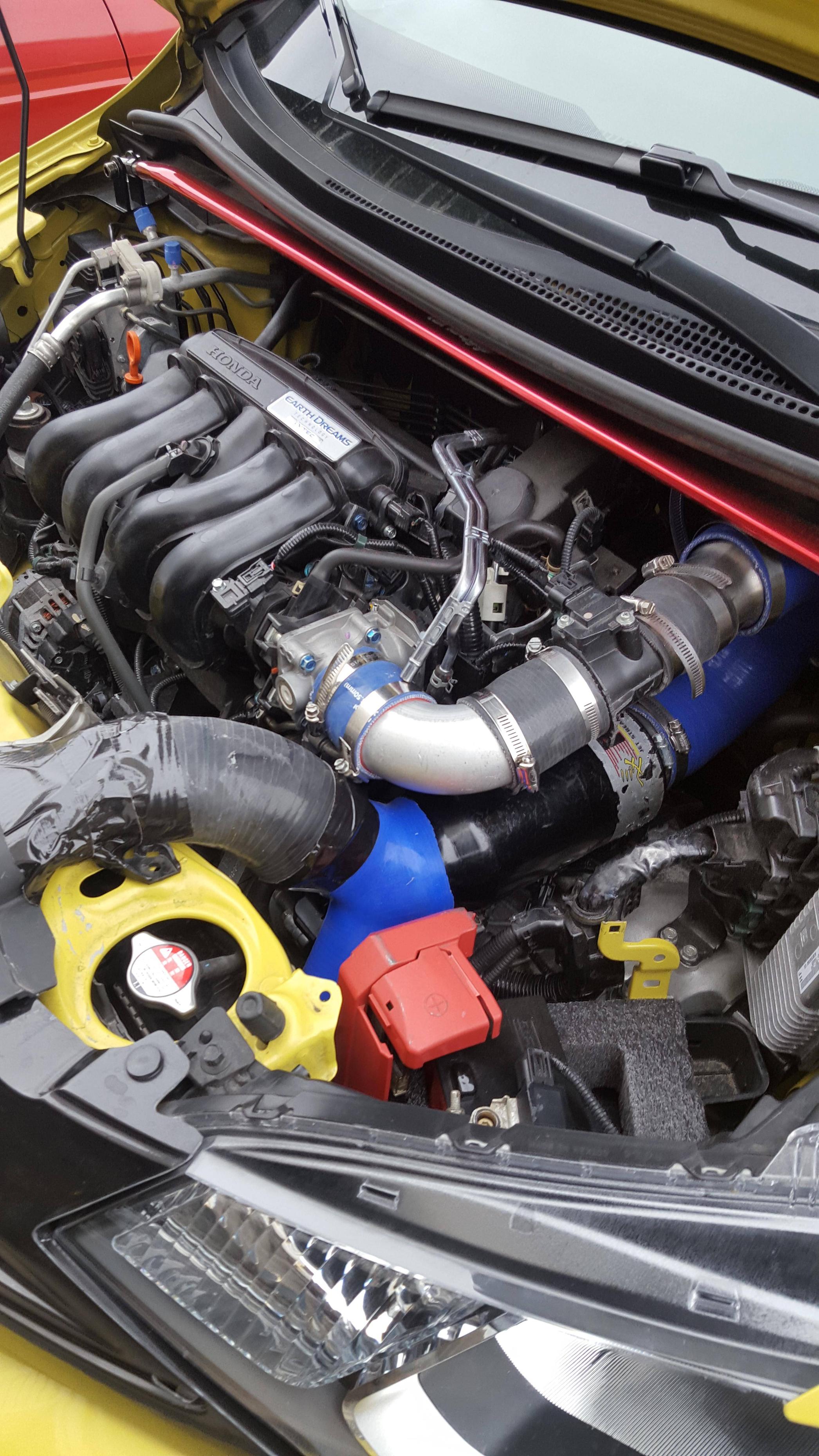
I had some time this morning to work on the PRM intake. The short ram worked great. Tested it last night and this morning at the dragstrip. Posted the time slips and video in another thread.
I got the PRM intake together. It's a very crude setup. The idea was there so I had to get it completed. The battery was reset and I drove it down the highway. So far, so good. I don't like it though. It's not exactly the way I had planned but I had to work with the parts I had on hand. The 2" piping from the throttle body is too long. I had a transition piece that widened right after the maf sensor and the maf sensor was attached to the throttle body. That part is just too long. Uugghhh!


 tuck it where it needs to go. I use the 1/8 inch semi rigid air line from napa. Its used to plumb air lines on some trucking applications and to plumb ice makers, uses simple press fit fittings. The hole is not posted at the air stream it just needs to be in the pressure zone you wan to measure. Aero effect starts at about 25 and is exponential as speed increases.. Most mag gauges have a tell tale that will show the highest reading attained.. A carb sync bourbon tube setup works too. Use WATER not mercury for this purpose. (Inches of water is how most of the is measurement is done.. )