
No splicing factory wires installation of amplifier and speakers


Thread Starter
|
Member
Joined: Jan 2014
Posts: 273
From: City of Angels

No splicing factory wires installation of amplifier and speakers
Thank you all for the info that I have been able to gather before I went on and added a Clarion XC1410 amplifier and the Infinity Kappa 62.9i speakers to both front/rear doors. This is what I did..
Setup:
Setup Harnesses:
-- a. 1x male harness (PN: Metra 71-1729 Harness or Best Kits BHO1729)
-- b. 2x female harness (PN: Metra 70-1729 Harness or Best Kits BHA1729)
---- a. The harness is missing 4 pins (2 on top row and 2 on the bottom row)
---- b. Missing pins: A11, A13, A22 & A23 (See figure below for reference)
------ i. https://www.fitfreak.net/forums/3rd-...in-layout.html
---- c. Pin A21 (Remote On - See figure below for reference) will not be in use
------ i. I wired the Remote On to the A24 pin (remember remote on needs very little power: ~0.5amp)
-- c. Pull 4 pins from the one female harnesses to populate pins: A11, A13, A22 & A23 on the other harness � Instruction below
a.
Setup Amplifier:
-- a. 1 x amplifier (Clarion CX1410)
---- a.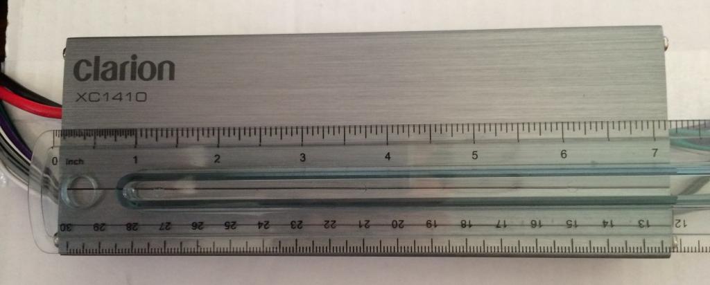
---- b. compact and able to provide 4 x 75 Watts @ 2 ohms (To power 2 ohms speakers)
------ i. ---- c. THD at rated RMS Power: 0.1%
------ i. http://www.crutchfield.com/S-ZHQ1LDk...ion-XC1410.htm
-- b. 1 x small piece of solid wood
---- a. Cut to: 9� x 3� x ��
-- c. Drill holes to the wood at the side/end: To allow for cable ties.
-- d. Mount amplifier to piece of wood (Don�t want amplifier touching any metal part on the car)
---- a.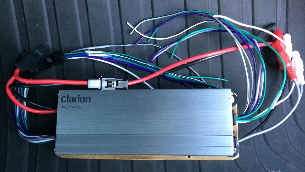
---- b.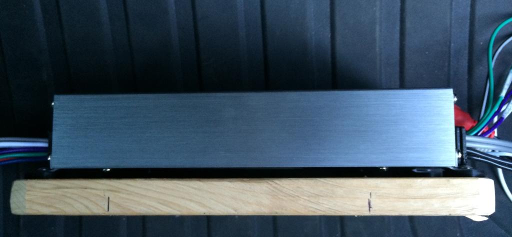
Setup Speakers:
-- a. 2x Infinity Kappa 62.9i (total 4 speakers)
---- a. ---- b. I originally was going to go with the Infinity Kappa 62.11i. Thank you FitFreak member (Payluder) for a really good deal on the 62.9i.
-- b. 2x Scosche SHHA02B
---- a.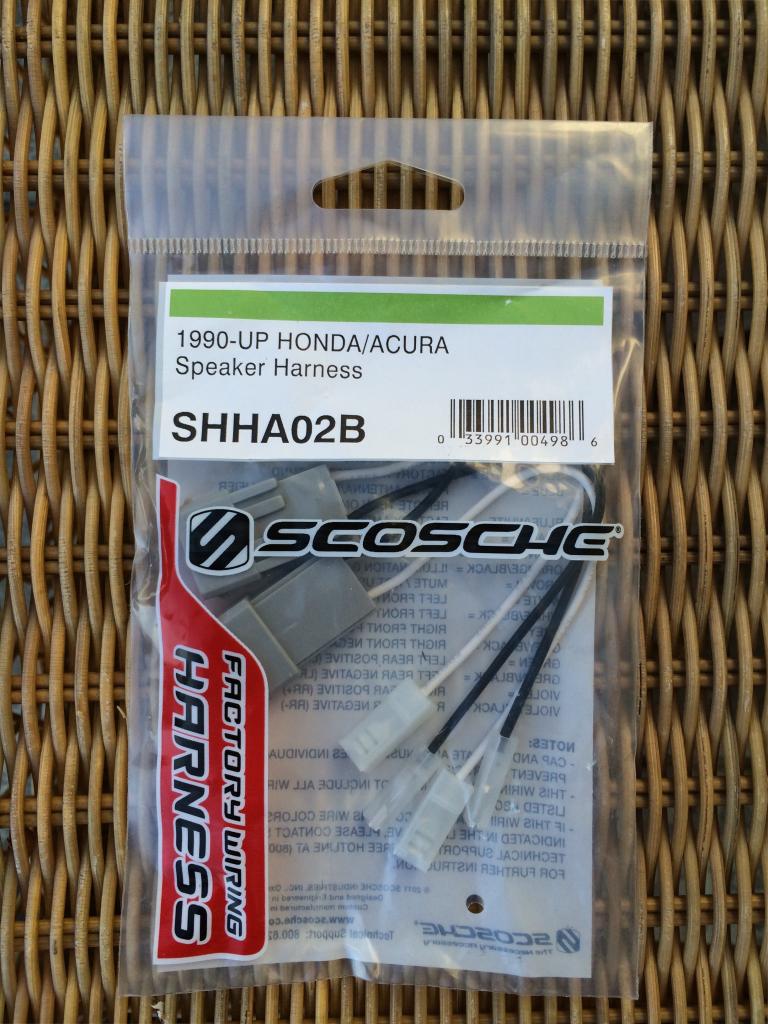
---- b. 1 set to the front speakers, 1 set to the back
---- c. Cut the wires and screw them to the crossover on the speakers
---- d.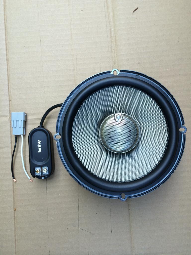
-- c. 2x Scosche SAHC634
---- a.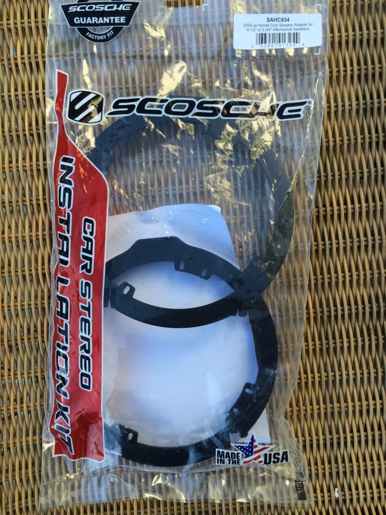
---- b. 1 set to the front speakers, 1 set to the back
---- c. Note: The adapter will bend a little creating a gap as you screw it to the door
------ i. I apply small strip of the sound deadener I have to fill the gap to both the speaker and door sides before screwing it to the door
Connect harnesses and Amplifier together:
-- a. I Use butt connectors and heat shrink tubing/heat gun
-- b. Connects the speakers wires from the Metra 71-1729 harness to the Clarion XC1410 Amplifier
-- c. Connects A11, A13, A22 & A23 from the Metra 71-1729 harness directly to Metra 70-1729 harness
-- d. Connects the A24 pin (ACC+ wire) from the Metra 71-1729 wire to both the Metra 70-1729 and the Remote On wire from the amplifier
---- a. Result: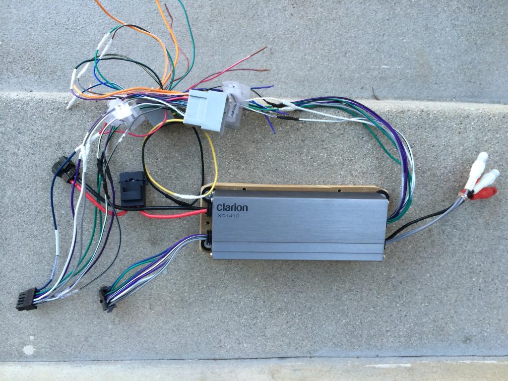
Setup:
Setup Harnesses:
-- a. 1x male harness (PN: Metra 71-1729 Harness or Best Kits BHO1729)
-- b. 2x female harness (PN: Metra 70-1729 Harness or Best Kits BHA1729)
---- a. The harness is missing 4 pins (2 on top row and 2 on the bottom row)
---- b. Missing pins: A11, A13, A22 & A23 (See figure below for reference)
------ i. https://www.fitfreak.net/forums/3rd-...in-layout.html
---- c. Pin A21 (Remote On - See figure below for reference) will not be in use
------ i. I wired the Remote On to the A24 pin (remember remote on needs very little power: ~0.5amp)
-- c. Pull 4 pins from the one female harnesses to populate pins: A11, A13, A22 & A23 on the other harness � Instruction below
a.
Setup Amplifier:
-- a. 1 x amplifier (Clarion CX1410)
---- a.

---- b. compact and able to provide 4 x 75 Watts @ 2 ohms (To power 2 ohms speakers)
------ i. ---- c. THD at rated RMS Power: 0.1%
------ i. http://www.crutchfield.com/S-ZHQ1LDk...ion-XC1410.htm
-- b. 1 x small piece of solid wood
---- a. Cut to: 9� x 3� x ��
-- c. Drill holes to the wood at the side/end: To allow for cable ties.
-- d. Mount amplifier to piece of wood (Don�t want amplifier touching any metal part on the car)
---- a.

---- b.

Setup Speakers:
-- a. 2x Infinity Kappa 62.9i (total 4 speakers)
---- a. ---- b. I originally was going to go with the Infinity Kappa 62.11i. Thank you FitFreak member (Payluder) for a really good deal on the 62.9i.
-- b. 2x Scosche SHHA02B
---- a.

---- b. 1 set to the front speakers, 1 set to the back
---- c. Cut the wires and screw them to the crossover on the speakers
---- d.

-- c. 2x Scosche SAHC634
---- a.

---- b. 1 set to the front speakers, 1 set to the back
---- c. Note: The adapter will bend a little creating a gap as you screw it to the door
------ i. I apply small strip of the sound deadener I have to fill the gap to both the speaker and door sides before screwing it to the door
Connect harnesses and Amplifier together:
-- a. I Use butt connectors and heat shrink tubing/heat gun
-- b. Connects the speakers wires from the Metra 71-1729 harness to the Clarion XC1410 Amplifier
-- c. Connects A11, A13, A22 & A23 from the Metra 71-1729 harness directly to Metra 70-1729 harness
-- d. Connects the A24 pin (ACC+ wire) from the Metra 71-1729 wire to both the Metra 70-1729 and the Remote On wire from the amplifier
---- a. Result:

Thread Starter
|
Member
Joined: Jan 2014
Posts: 273
From: City of Angels
Installation:
Amplifier Installation:
-- a. Remove the head unit and remove the glove compartment
-- b. Install the amplifier right above the glove compartment
-- c. Before cable tie:

-- d. Result with cable tie:

-- e. I also grounded the amplifier to the bolt on the metal bar (upper right on the picture above)
-- f. Power to the amp:

---- a. The Clarion XC1410 does not draw a lot of power. If your amp draws a lot of power, you need to connect it directly to the battery.
-- g. Connects the Metra 71-1729 to the HU and the Metra 70-1729 to the factory�s harness
-- h. After testing and that they are all working, put the HU back.
Speakers Installation:
-- a. While I was at it, I decided to add sound deadener to the doors
---- a. Result:

---- b. I did later add sound deadener to the trunk and trunk door too:
-- b. With all the preparation done, it was pretty straight forward
---- a. Speakers comparison between Infinity Kappa 62.9i vs factory speaker:

---- b. Note: And again, I cut a couple thin strips of the sound deadener and attach them to both the door and speakers side on the speaker adapters, resulting in snug fit.
---- c. Result:


Someone that spends his life on FitFreak.net
Joined: Mar 2014
Posts: 1,116
From: Hawaii: relocated to Western Canada Sept, 2015
There are three wires in metra that are missing from the OEM HU connectors. Without those you lose the steering wheel controls for the HU. Gotta share how you overcame that. It will help all others for sure.
Had both the same male/female aftermarket connectors but decided to splice, to maintain all the OEM controls with the HU.
Great post and pics. Gotta let us know your impressions of the sound result. Liking your set-up cause the amp has the perfect footprint for our "small" Fits!!! Good job!!!!
Had both the same male/female aftermarket connectors but decided to splice, to maintain all the OEM controls with the HU.
Great post and pics. Gotta let us know your impressions of the sound result. Liking your set-up cause the amp has the perfect footprint for our "small" Fits!!! Good job!!!!
Thread Starter
|
Member
Joined: Jan 2014
Posts: 273
From: City of Angels
Picture with a ruler on the amp gives you the size and the picture of the amp above the glove compartment are not enough?
Thread Starter
|
Member
Joined: Jan 2014
Posts: 273
From: City of Angels
There are three wires in metra that are missing from the OEM HU connectors. Without those you lose the steering wheel controls for the HU. Gotta share how you overcame that. It will help all others for sure.
Had both the same male/female aftermarket connectors but decided to splice, to maintain all the OEM controls with the HU.
Great post and pics. Gotta let us know your impressions of the sound result. Liking your set-up cause the amp has the perfect footprint for our "small" Fits!!! Good job!!!!
Had both the same male/female aftermarket connectors but decided to splice, to maintain all the OEM controls with the HU.
Great post and pics. Gotta let us know your impressions of the sound result. Liking your set-up cause the amp has the perfect footprint for our "small" Fits!!! Good job!!!!
Setup Harnesses:
-- a. 1x male harness (PN: Metra 71-1729 Harness or Best Kits BHO1729)
-- b. 2x female harness (PN: Metra 70-1729 Harness or Best Kits BHA1729)
---- a. The harness is missing 4 pins (2 on top row and 2 on the bottom row)
---- b. Missing pins: A11, A13, A22 & A23 (See figure below for reference)
------ i. https://www.fitfreak.net/forums/3rd-g...in-layout.html
---- c. Pin A21 (Remote On - See figure below for reference) will not be in use
------ i. I wired the Remote On to the A24 pin (remember remote on needs very little power: ~0.5amp)
-- c. Pull 4 pins from the one female harnesses to populate pins: A11, A13, A22 & A23 on the other harness � Instruction below
a.
Someone that spends his life on FitFreak.net
Joined: Mar 2014
Posts: 1,116
From: Hawaii: relocated to Western Canada Sept, 2015
Damn!!! I should've watched the video. Not only just now, but last Oct. when I was doing my stereo install. To think I even had a donor harness. Absolutely effective method of getting them out without ruining the pins. Initially I tied using sharp pointed object but that just ruined the retaining portion of the pins.
You've just helped a whole ton of future FF installers obtain the ability of maintaining the steering controls without splicing.

Member
Joined: Jul 2014
Posts: 227
From: Los Angeles
How is the sound staging with this?
The Clarion amp doesn't have gain control, and from some of the other threads on this, the stock stereo doesn't put out equal power to the rear channels.
I assume with this setup, you aren't changing that front-rear bias?
I suppose you could change it by using the line-level inputs + 2 two-channel LOC's with gain control.
Member
Joined: Jul 2014
Posts: 227
From: Los Angeles
also can you explain what you did with the add a fuse.
I think you used a regular micro add-a-fuse, with a 25A fuse (its clear), but then you don't use the output pigtail, and i see you used one of those metal fuse hijackers...
First, which slot did you plug it into? an empty powered slot? Or did you remove a fuse, plug in the add-a-fuse, and then plugged two new fuses into it...
Can you please clarify what you did power wise. I think the reason you didnt use the output pigtail because thats 16 gauge wire, not enough for 25A.
Thread Starter
|
Member
Joined: Jan 2014
Posts: 273
From: City of Angels
also can you explain what you did with the add a fuse.
I think you used a regular micro add-a-fuse, with a 25A fuse (its clear), but then you don't use the output pigtail, and i see you used one of those metal fuse hijackers...
First, which slot did you plug it into? an empty powered slot? Or did you remove a fuse, plug in the add-a-fuse, and then plugged two new fuses into it...
Can you please clarify what you did power wise. I think the reason you didnt use the output pigtail because thats 16 gauge wire, not enough for 25A.
I think you used a regular micro add-a-fuse, with a 25A fuse (its clear), but then you don't use the output pigtail, and i see you used one of those metal fuse hijackers...
First, which slot did you plug it into? an empty powered slot? Or did you remove a fuse, plug in the add-a-fuse, and then plugged two new fuses into it...
Can you please clarify what you did power wise. I think the reason you didnt use the output pigtail because thats 16 gauge wire, not enough for 25A.
You are right on that I didn't use the output pigtail as it doesn't have the right size wire for the power. Therefore I had to use an ATM Mini Fuse Tap and connect my 8 gauge(international) wire to the fuse box.
I plugged into an empty slot in this case. Though it is fine if you pull a fuse out of the existing slot and then plug the add on there.
- Basically the back of the fuse panel is basically a plate with pins for you to added the fuse to(similar concept to the power panel for a house) to distribute power to multiple devices with fuses for protection.
Thread Starter
|
Member
Joined: Jan 2014
Posts: 273
From: City of Angels
How is the sound staging with this?
The Clarion amp doesn't have gain control, and from some of the other threads on this, the stock stereo doesn't put out equal power to the rear channels.
I assume with this setup, you aren't changing that front-rear bias?
I suppose you could change it by using the line-level inputs + 2 two-channel LOC's with gain control.
The Clarion amp doesn't have gain control, and from some of the other threads on this, the stock stereo doesn't put out equal power to the rear channels.
I assume with this setup, you aren't changing that front-rear bias?
I suppose you could change it by using the line-level inputs + 2 two-channel LOC's with gain control.
Member
Joined: Jul 2014
Posts: 227
From: Los Angeles
Using these exact components, and using speaker-level inputs, are you getting any noise? Hissing or alternator noise? When the volume is all the way down, are you hearing any noise?
Also, using the speaker level inputs, since there is no gain control, does the relative volume of the head unit match the new amp?
Meaning, does volume level 15 sound like volume level 15 from before?
or is volume level 5 now = volume level 15 before. Of course this depends on how efficient your speakers are.
Thread Starter
|
Member
Joined: Jan 2014
Posts: 273
From: City of Angels
Using these exact components, and using speaker-level inputs, are you getting any noise? Hissing or alternator noise? When the volume is all the way down, are you hearing any noise?
Also, using the speaker level inputs, since there is no gain control, does the relative volume of the head unit match the new amp?
Meaning, does volume level 15 sound like volume level 15 from before?
or is volume level 5 now = volume level 15 before. Of course this depends on how efficient your speakers are.
Also, using the speaker level inputs, since there is no gain control, does the relative volume of the head unit match the new amp?
Meaning, does volume level 15 sound like volume level 15 from before?
or is volume level 5 now = volume level 15 before. Of course this depends on how efficient your speakers are.
Nope, no funny noise. With the volume all the way down, no noise. Generally when you have noise is due to either the amp enclosure touches something metal on the car, the ground wire is too long, ground wire is not connected to the appropriate place for ground.
With the Infinity speakers, volumne 15 is now louder than the factory speakers. I would say, volume 8 now(Infinity Kappa 62.9i) is like volume 14 under factory speakers.
Member
Joined: Jul 2014
Posts: 227
From: Los Angeles
I know you don't sit in the back seats, but I'd like to point out for other people doing this using this amp, you ARE keeping the front volume bias. I would estimate the fronts are 30-50% louder than the rear speakers. If you are going to tap a sub into the speaker level outs, I might suggest tapping the front speakers instead of the rear. I just finished installing a small sub, and the volume of the sub balanced way better with the front speakers than the rear.
Example: decent listening volume up front means the rears are barely doing anything. If you use the rear speakers for your sub, it won't match what you are hearing volume wise from the front. I suppose with a powerful enough sub you could match it. I am using a Kenwood KSC-SW11 in the rear.
Or you could set your fader a few clicks to the rear, but then the indicator isn't in the middle of the scale... And I'd prefer to keep the front bias when nobody is in the car.
Jacob

Thread
Thread Starter
Forum
Replies
Last Post
clay7160
2nd Gen GE8 Specific Fit Interior Modifications Sub-Forum
7
Jul 31, 2011 12:16 PM
CuTeBoi
Fit Interior Modifications
2
Jun 8, 2007 06:41 AM